] dlc configuration block – Flintec FT-15D User Manual
Page 25
FT-15(D) Technical Manual, Rev. 1.02 August 2010
Page 25 of 52
9.2 Defining the Digital Load cells (for FT-15D only)
9.2.1 Digital Load Cell Addressing
The parameter group [22-] is used for defining and addressing the DLCs.
[22-] DLC Configuration Block
In this section the DLCs are introduced to the indicator.
[220 X] DLC Type
0 = RC3D
This parameter must be set to “0” for type RC3D digital load cell.
[221 XX] Quantity of DLC
Enter the quantity of DLCs used in the scale. The quantity can be selected between 1 and 16.
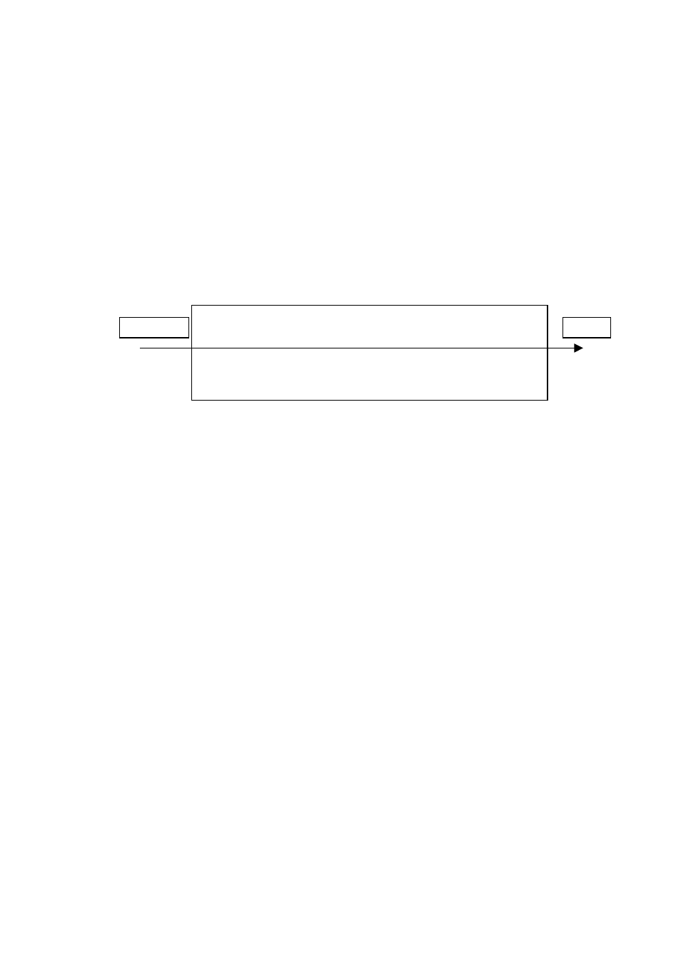
[222 ] DLC Addressing
The following diagram shows the addressing principles of the DLCs in a weighbridge / truck scale. The
numbers in the diagram show the DLC addressing principle for easy eccentricity adjustment.
Figure 9.1
The addressing principles of the DLC’s in a weighbridge / truck scale
The serial numbering system of the indicator is 9 digits. The last 6 digits will be entered after entering the
first 3 digits. If the S/N is less than 9 digits, the unused digits on the left must be entered as 0. For
example, if the serial number is 1234567, 001234567 must be entered as a serial number.
For addressing of DLCs, press the
The messages [222 YY] and [ XXXXXX ] will be displayed alternately.
Here: “YY” DLC
number
/address
“X”
Last 6 digits of the DLC’s serial number
If you press
[20-].
For entering the serial number of the DLC to address 1, press the
digits of the S/N. Press the
the digits of the S/N. After entering of the S/N, press the
last DLC serial number to the indicator, the [20- ] is shown on the display. This means all load cells are
addressed and ready to operate in the scale.
Important hint:
When addressing the connected Type RC3D load cells, the load cells should always be
loaded. If the load cells are unloaded, FT-15D may show a DLC input error.
For replacing any load cell, you have to re-address the new load cell in parameter [222]. After installing
the new load cell, turn on the indicator. Enter parameter [222] and then access the load cell address of
the replaced DLC. Enter the serial number of the new load cell as described in the previous paragraph.
Note: It is always assumed that the RS485 load cell bus system is correctly terminated, please see the
manual of the installed junction box.
1
2
3
10
9
8
7
6
5
4
Entrance
Exit