4 • installation instructions & diagrams – FingerTec Ingressus IV User Manual
Page 14
14
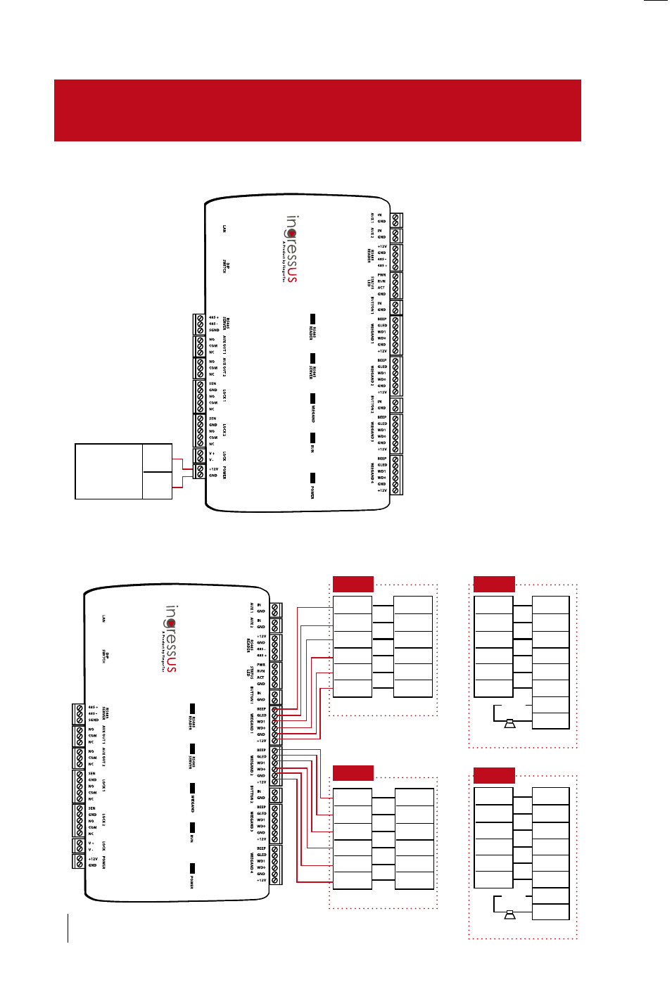
i-Kadex
IN
BEEP
GLED
WD1
WD0
GND
+12v
BEEP
GLED
WD1
WD0
GND
+12v
Note:
1. Only supply 12VDC 3A to
Ingressus. Recommended to
use switching power supply
with stable 12VDC 3A out-
put.
2. Check to make sure the POW-
ER LED lights up in red color.
3. DO NOT share the switching
power with any other Ingres-
sus, door lock systems or
other devices.
4. Make sure backup power is
available to support Ingres-
sus during power failure.
5. TURN OFF power for Ingres-
sus before you continue to
the next step.
12VDC 3 A
Switching
power
supply
+12V
GND
i-Kadex
BEEP
GLED
WD1
WD0
GND
+12v
BEEP
GLED
WD1
WD0
GND
+12v
k-Kadex
IN
BEEP
GLED
WD1
WD0
GND
+12v
RLED
GLED
WD1
WD0
GND
+12v
Bell+
Bell_
OUT
Power
k-Kadex
OUT
BEEP
GLED
WD1
WD0
GND
+12v
RLED
GLED
WD1
WD0
GND
+12v
Bell+
Bell_
Power
OR
OR
4 • INSTALLATION INSTRUCTIONS &
DIAGRAMS
POwER-UP INGRESSUS
CONNECTING TO wIEGAND READER
(k-Kadex, i-Kadex)