Parameters – EVCO EVC30S40J7XXX09 User Manual
Page 7
7/13
3. PARAMETERS
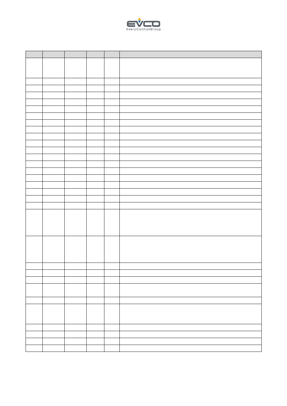
PAR. MIN.
MAX. U.M. DEF WORK SET-POINT
P0
0
1
---
0
temperature unit of measurement
0
= °C
1 =
°F
P1 -25/-50
25/50 °C/°F
0 probe
1
offset
P2 P3 P4 °C/°F
185
work
set-point
P3 0
P4 °C/°F
0 set-point
minimum
P4 P3 999 °C/°F
195
set-point
maximum
P5
0
1
---
1
pre-heat enabling from start
P6
1
99
°C/°F 5
temperature differential in range
P7
0
120
sec
20
temperature timeout in range
P8 P3 P4 °C/°F
100
pre-heat/preservation
set-point
P9
1
240
sec
40
pre-heat cycle time
P10 0
100
---
30
on percentage during pre-heat
P11 -99
99
°C/°F 0 band
offset
P12 1
250 °C/°F 18 proportional
band
P13 0
999
sec
300 integral action time (0 = no action)
P14 0
240
sec
40
derivative action time (0 = no action)
P15 1
240 sec 70 cycle
time
P16 0
120
sec
0
output minimum switch-over time
P17 1
99
°C/°F 1
maximum alarm differential ("AL" code)
P18 0
999
°C/°F 15
maximum alarm threshold ("AL" code)
P19 0
240
min
2
maximum alarm delay ("AL" code)
P20 0
2
---
2
maximum alarm type (AL)
0 = no alarm
1 = absolute (i.e. P18)
2 = relative to the work set-point (P2+P18)
P21 -1
120
sec
15
buzzer on time when work set-point P2 is reached for
the first time
0 = function disabled
-1 = sound active until silenced manually
P22 0
80/175 °C/°F 70
board temperature alarm threshold
P23 5
240 sec
sampling
time
P24 0
1
---
0
enabling of cycle synchronisation
P25 85
100
---
90
minimum percentage requested to re-synchronise the
cycle if the output is not active
P26 20/65 65/150 °C/°F 50 fans
set
P27 -1
120
sec
15
buzzer on duration o expiry of timer
0 = function disabled
-1 = sound active until silenced manually
P28 0
1
---
0
digital input 1 polarity (Peak cut) 0=N.O.
P29 0
1
---
0
digital input 2 polarity (Overheating limiter) 0=N.O.
P30 0
1
---
0
enabling of probe 2
P31 -25/-50 25/50 °C/°F 0 probe
2
offset