Basic i/o – Digilent 410-182P-KIT User Manual
Page 18
Nexys3 Reference Manual
Doc: 502-182
page 18 of 22
Basic I/O
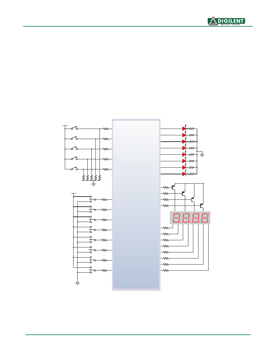
The Nexys3 board includes eight slide switches, five push buttons, eight individual LEDs, and a four
digit seven-segment display. The pushbuttons and slide switches are connected to the FPGA via
series resistors to prevent damage from inadvertent short circuits (a short circuit could occur if an
FPGA pin assigned to a pushbutton or slide switch was inadvertently defined as an output). The
pushbuttons are "momentary" switches that normally generate a low output when they are at rest, and
a high output only when they are pressed. Slide switches generate constant high or low inputs
depending on their position.
The eight individual high-efficiency LEDs are anode-connected to the FPGA via 390-ohm resistors, so
they will turn on when a logic high voltage is applied to their respective I/O pin. Additional LEDs that
are not user-accessible indicate power-on, FPGA programming status, and USB and Ethernet port
status.
Spartan 6
A8
D9
C4
V9
M8
N8
U8
V8
C9
T5
BTNL
BTNR
BTNU
BTND
SW0
SW1
SW2
SW3
SW4
SW5
SW6
SW7
3.3V
LD0
LD1
LD2
LD3
LD4
LD5
LD6
LD7
3.3V
LEDs
AN3
AN2
AN1
AN0
T9
T10
U16
V16
U15
V15
M11
N11
R11
T11
P17
P18
N15
N16
T17
T18
U17
U18
M14
N14
L14
CA
CB
CC
CD
CE
CF
CG
DP
M13
7-seg
Display
Slide
Switches
3.3V
Buttons
B8
BTNS