Keyboard – Digilent 410-182P-KIT User Manual
Page 13
Nexys3 Reference Manual
Doc: 502-182
page 13 of 22
incorrect bit files will automatically be rejected. Note the PIC24 reads the FPGA's mode, init, and done
pins, and can drive the PROG pin as a part of the programming sequence.
HID Controller
To access the USB host controller, EDK designs
can use the standard PS/2 core (non-EDK designs
can use a simple state machine).
Mice and keyboards that use the PS/2 protocol
1
use a two-wire serial bus (clock and data) to
communicate with a host device. Both use 11-bit
words that include a start, stop, and odd parity bit,
but the data packets are organized differently, and
the keyboard interface allows bi-directional data
transfers (so the host device can illuminate state
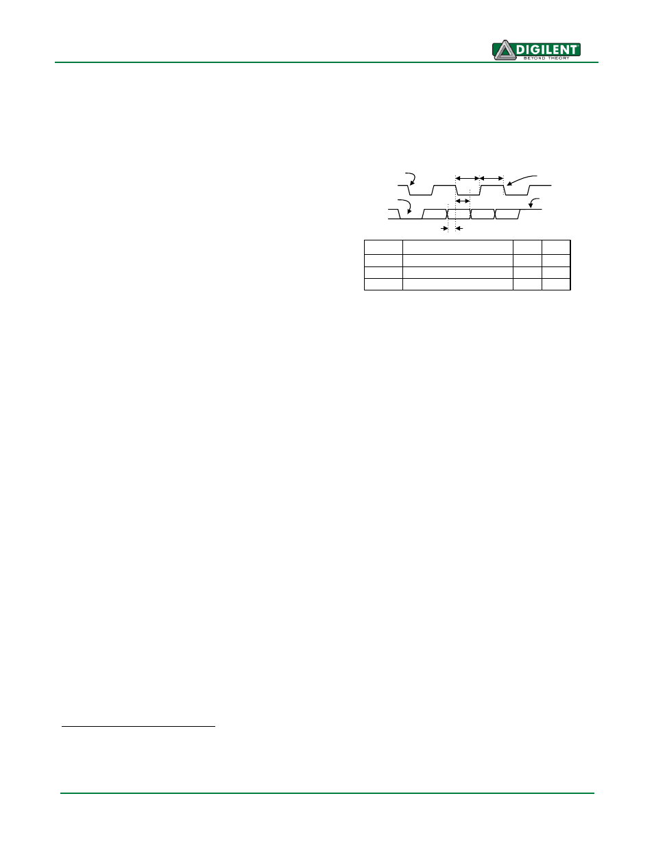
LEDs on the keyboard). Bus timings are shown in
the figure. The clock and data signals are only driven when data transfers occur, and otherwise they
are held in the idle state at logic ‘1’. The timings define signal requirements for mouse-to-host
communications and bi-directional keyboard communications. A PS/2 interface circuit can be
implemented in the FPGA to create a keyboard or mouse interface.
Keyboard
The keyboard uses open-collector drivers so the keyboard, or an attached host device, can drive the
two-wire bus (if the host device will not send data to the keyboard, then the host can use input-only
ports).
PS/2-style keyboards use scan codes to communicate key press data. Each key is assigned a code
that is sent whenever the key is pressed. If the key is held down, the scan code will be sent
repeatedly about once every 100ms. When a key is released, an F0 key-up code is sent, followed by
the scan code of the released key. If a key can be shifted to produce a new character (like a capital
letter), then a shift character is sent in addition to the scan code, and the host must determine which
ASCII character to use. Some keys, called extended keys, send an E0 ahead of the scan code (and
they may send more than one scan code). When an extended key is released, an E0 F0 key-up code
is sent, followed by the scan code. Scan codes for most keys are shown in the figure. A host device
can also send data to the keyboard. Below is a short list of some common commands a host might
send.
ED
Set Num Lock, Caps Lock, and Scroll Lock LEDs. Keyboard returns FA after receiving ED,
then host sends a byte to set LED status: bit 0 sets Scroll Lock, bit 1 sets Num Lock, and bit 2
sets Caps lock. Bits 3 to 7 are ignored.
EE
Echo (test). Keyboard returns EE after receiving EE.
F3
Set scan code repeat rate. Keyboard returns F3 on receiving FA, then host sends second byte
to set the repeat rate.
1
Not all keyboard manufacturers strictly adhere to the PS/2 specifications; some keyboards may not
produce the proper signaling voltages or use the standard communication protocols. Compatibility
with the USB host may vary between different keyboards.
T
CK
T
SU
Clock time
Data-to-clock setup time
30us
5us
50us
25us
Symbol
Parameter
Min
Max
T
HLD
Clock-to-data hold time
5us
25us
Edge 0
‘0’ start bit
‘1’ stop bit
Edge 10
Tsu
T
hld
Tck Tck