Display surface – Digilent 410-182P-KIT User Manual
Page 16
Nexys3 Reference Manual
Doc: 502-182
page 16 of 22
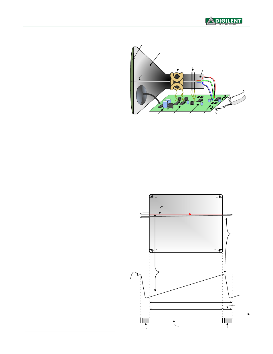
those rays are fed by the current that flows into the cathodes. These particle rays are initially
accelerated towards the grid, but they soon
fall under the influence of the much larger
electrostatic force that results from the entire
phosphor-coated display surface of the CRT
being charged to 20kV (or more). The rays
are focused to a fine beam as they pass
through the center of the grids, and then they
accelerate to impact on the phosphor-coated
display surface. The phosphor surface glows
brightly at the impact point, and it continues
to glow for several hundred microseconds
after the beam is removed. The larger the
current fed into the cathode, the brighter the
phosphor will glow.
Between the grid and the display surface, the
beam passes through the neck of the CRT
where two coils of wire produce orthogonal electromagnetic fields. Because cathode rays are
composed of charged particles (electrons), they can be deflected by these magnetic fields. Current
waveforms are passed through the coils to produce magnetic fields that interact with the cathode rays
and cause them to transverse the display surface in a “raster” pattern, horizontally from left to right
and vertically from top to bottom. As the cathode ray moves over the surface of the display, the
current sent to the electron guns can be increased or decreased to change the brightness of the
display at the cathode ray impact point.
Information is only displayed
when the beam is moving in the “forward” direction (left to right and top
to bottom), and not during the time the
beam is reset back to the left or top
edge of the display. Much of the
potential display time is therefore lost
in “blanking” periods when the beam is
reset and stabilized to begin a new
horizontal or vertical display pass. The
size of the beams, the frequency at
which the beam can be traced across
the display, and the frequency at which
the electron beam can be modulated
determine the display resolution.
Modern VGA displays can
accommodate different resolutions,
and a VGA controller circuit dictates
the resolution by producing timing
signals to control the raster patterns.
The controller must produce
synchronizing pulses at 3.3V (or 5V) to
set the frequency at which current
flows through the deflection coils, and
it must ensure that video data is
applied to the electron guns at the
correct time. Raster video displays
define a number of “rows” that
Current
waveform
through
horizontal
defletion
coil
Stable current ramp - information
is displayed during this time
Retrace - no
information
displayed
during this
time
Total horizontal time
Horizontal display time
Horizontal sync signal
sets retrace frequency
retrace
time
time
HS
"back porch"
"front porch"
Display Surface
640 pixels per row are displayed
during forward beam trace
pixel 0,639
pixel 0,0
pixel 479,0
pixel 479,639
Anode (entire screen)
High voltage
supply (>20kV)
Deflection coils
Grid
Electron guns
(Red, Blue, Green)
gun
control
grid
control
deflection
control
R,G,B signals
(to guns)
Cathode ray tube
Cathode ray
VGA
cable