1 hid controller – Digilent 410-292P-KIT User Manual
Page 11
Nexys4 DDR™ FPGA Board Reference Manual
Copyright Digilent, Inc. All rights reserved.
Other product and company names mentioned may be trademarks of their respective owners.
Page 11 of 29
Artix-7
F4
PIC24FJ128
PS2_CLK
B2
HOST (J5)
2
PS2_DAT
FPGA
Config
microSD
7
FPGA
Config
User I/O
SD MICRO (J1)
SD/USB (JP2)
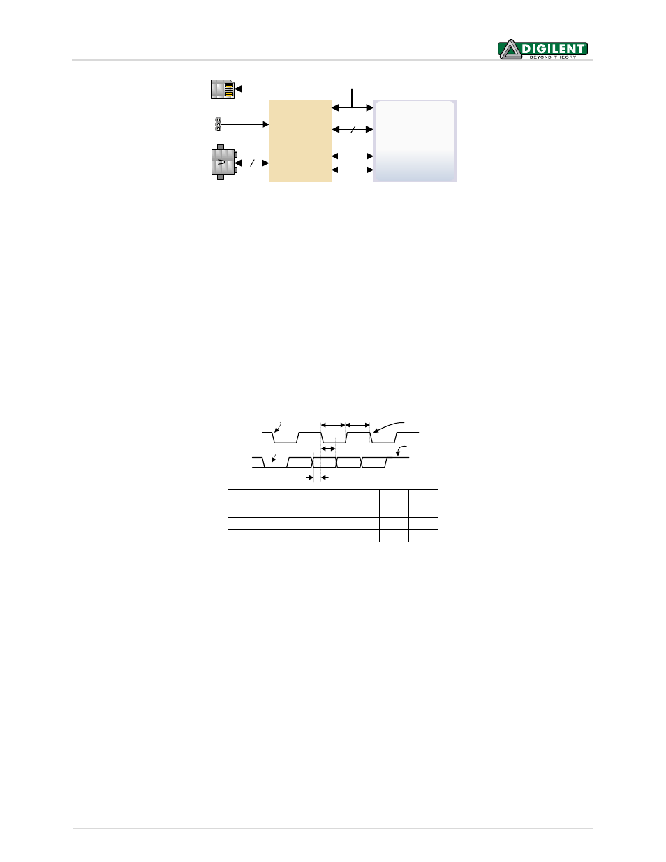
Figure 7. Nexys4 DDR PIC24 connections.
8.1 HID Controller
The Auxiliary Function microcontroller hides the USB HID protocol from the FPGA and emulates an old-style PS/2
bus. The microcontroller behaves just like a PS/2 keyboard or mouse would. This means new designs can re-use
existing PS/2 IP cores. Mice and keyboards that use the PS/2 protocol use a two-wire serial bus (clock and data) to
communicate with a host. On the Nexys4 DDR, the microcontroller emulates a PS/2 device while the FPGA plays
the role of the host. Both the mouse and the keyboard use 11-bit words that include a start bit, data byte (LSB
first), odd parity, and stop bit, but the data packets are organized differently, and the keyboard interface allows bi-
directional data transfers (so the host device can illuminate state LEDs on the keyboard). Bus timings are shown in
Figure 8.
T
CK
T
SU
Clock time
Data-to-clock setup time
30us
5us
50us
25us
Symbol
Parameter
Min
Max
T
HLD
Clock-to-data hold time
5us
25us
Edge 0
‘0’ start bit
‘1’ stop bit
Edge 10
Tsu
T
hld
Tck Tck
CLOCK
DATA
Figure 8. PS/2 device-to-host timing diagram.
The clock and data signals are only driven when data transfers occur; otherwise, they are held in the idle state at
high-impedance (open-drain drivers). This requires that when the PS/2 signals are used in a design, internal pull-
ups must be enabled in the FPGA on the data and clock pins. The clock signal is normally driven by the device, but
may be held low by the host in special cases. The timings define signal requirements for mouse-to-host
communications and bi-directional keyboard communications. A PS/2 interface circuit can be implemented in the
FPGA to create a keyboard or mouse interface.
When a keyboard or mouse is connected to the Nexys4 DDR, a “self-test passed” command (0xAA) is sent to the
host. After this, commands may be issued to the device. Since both the keyboard and the mouse use the same
PS/2 port, one can tell the type of device connected using the device ID. This ID can be read by issuing a Read ID
command (0xF2). Also, a mouse sends its ID (0x00) right after the “self-test passed” command, which distinguishes
it from a keyboard.