Toshiba IK-M41R2 User Manual
Page 15
Attention! The text in this document has been recognized automatically. To view the original document, you can use the "Original mode".
CLOCK output:
Shorting the land of MAIN board will allow the clock to be output from 9 pin (signal) and
8 pin (GND) of DCIN/SYNC terminal (12 pin connector) on the rear.
The clock output is 14.31818 MHz ± 50ppm.
VIDEO OUT C-coupling, DC direct connection output switching
The video out signal develops from both pins 4 (signal), 3 (GND) of the DC IN/SYNC termi
nal located on the rear side of the camera and the video terminal (BNC connector).
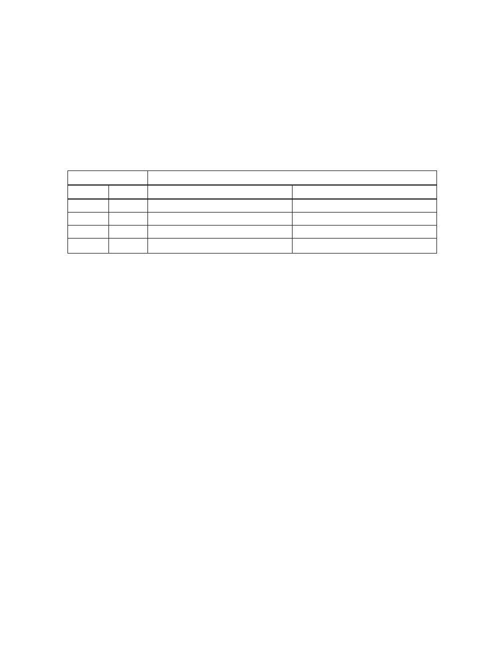
Setting No. 9 and No. 10 of the S308 mode switch can select either the DC direct connec
tion output (the video blanking signal except SYNC is fixed to GND.) or the C-coupling
output for the video output signal.
S308
VIDEO output
No. 9
No. 10
VIDEO (BNC connection)
DC IN/SYNC (pin 12)
OFF
OFF
C-coupling output
C-coupling output
OFF
ON
DC direct connection output
C-coupling output
ON
OFF
C-coupling output
DC direct connection output
ON
ON
DC direct connection output
DC direct connection output
15