Signal input/output, 1| ceitditioii, Ixlwmii sync, laput – Toshiba IK-M41R2 User Manual
Page 10: 3) specifications of ixternal owtput sigwgl
Attention! The text in this document has been recognized automatically. To view the original document, you can use the "Original mode".
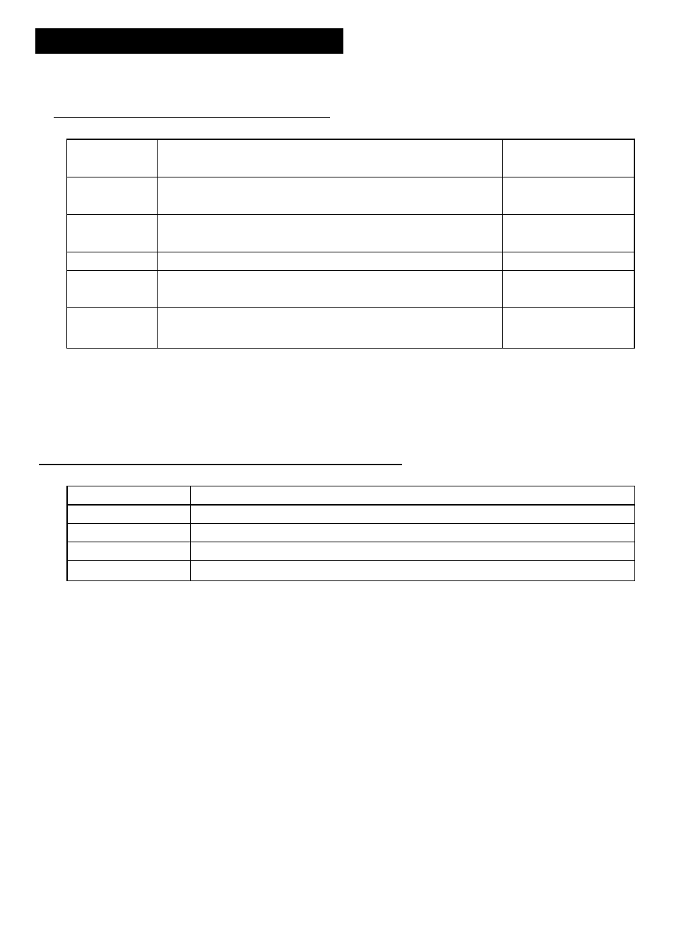
3. SIGNAL INPUT/OUTPUT
|1| Ceitditioii
o§
IxlWMii Sync, laput
1.HD
3.0±1.5Vp-p • Negative polarity • 75Q unbalanced
5.0±0.5Vp-p • Negative polarity • TTL level
6.0\is - 10.0p.s
2.VD
3.0±1.5Vp-p • Negative polarity • 75Q unbalanced
5.0±0.5Vp-p • Negative polarity • TTL level
3H to 9H
3. C-SYNC
3.0±1.5Vp-p • Negative polarity • 75Q unbalanced
5.0±0.5Vp-p • Negative polarity • TTL level
EIA-170A standards
4. VS/VBS
0.3±0.1Vp-p • 75Q unbalanced
EIA-170A standards
5. RR. VD
3.0±1.5Vp-p • Negative polarity • 75Q unbalanced
5.0±0.5Vp-p • Negative polarity • TTL level
3H to 9H
6. TRIGGER
3.0±1.5Vp-p • Negative polarity • 75Q unbalanced
5.0±0.5Vp-p • Negative polarity • TTL level
3H to 9H
NOTE: In case of VD, C-SYNC,
nal or VD terminal and
VSA/BS and RR. VD, use the connector for DC IN/SYNC termi-
input a signal selected dependent on the mode in use.
External sync, frequency range: Within ±1.0% against NTSC standards
[ (3) Specifications of Ixternal Owtput Sigwgl ]
1. VIDEO
I.OVp-p • 75Q unbalanced
2. VIDEO INDEX
5.0±0.5Vp-p • Positive polarity • Load impedance more than 10KQ
3. HD
5.0±0.5Vp-p • Negative polarity • Load impedance more than 10KQ
4. VD
5.0±0.5Vp-p • Negative polarity • Load impedance more than 10KQ
5. CLOCK
4.0±1.5Vp-p • 14.31813 MHz • Load impedance more than 1KQ
When HD and VD, common with HD IN and VD IN, are used for inputting, they cannot be
used for outputting. (Input/output can be selected by changing the internal connector.
Input: P304, Output: P305) CLOCK can be output by shorting the inner land.
Inner land for CLOCK
CKOUT
Inside of the camera
MAIN board
- Connectors
Output Input
10