3) 12 pin connecter (dc in/sync terminal) – Toshiba IK-M41R2 User Manual
Page 11
Attention! The text in this document has been recognized automatically. To view the original document, you can use the "Original mode".
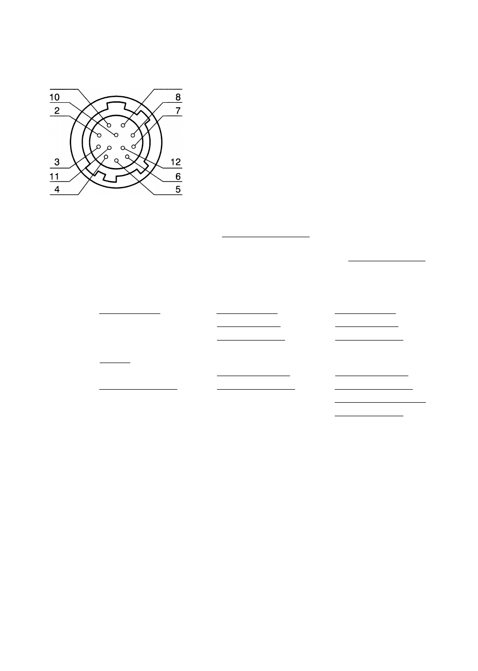
(3) 12 Pin Connecter (DC IN/SYNC terminal)
In case the signal is input/output directly from DC IN/SYNC terminal, connect as follows.
[ DC IN/SYNC terminal]
1
9
Type of connector to be used with DC IN/SYNC
terminal: HIROSE HR10A-10P-12S
Pin No.
VS/VBS/C-SYNC
External Sync. Mode
HD, VD
RESET RESTART/
One-pulse Trigger
Power GND
Power GND
Power GND
2*
Power +12V
Power +12V
Power +12V
VIDEO (GND)
VIDEO (GND)
VIDEO (GND)
VIDEO (Signal)
VIDEO (Signal)
VIDEO (Signal)
HD input (GND)
HD input (GND)
6*
VSA/BS/C-SYNC input
(Signal)
HD input (Signal)
HD input (Signal)
7*
VD input (Signal)
VD input (Signal)
CLK output (GND)
CLK output (Signal)
CLK output (GND)
CLK output (GND)
CLK output (Signal)
CLK output (Signal)
10
VIDEO INDEX (output)
11
TRIGGER (input)
12
VSA/BS/C-SYNC input
(GND)
VD input (GND)
VD input (GND)
CLOCK OUT requires to short the inner land.
-IMPORTANT
The one marked with * is parallely connected to HD, VD, and DC 12V IN terminals.
Input/output of the signal should be carried out from either one terminal only. (Do not
make connection simultaneously.)
11