Mounting angle and position of the bl-600 series, Connection and wiring – KEYENCE BL-600 Series User Manual
Page 3
3
CONNECTION AND WIRING
Power supply connections
Connect the 5 V DC power supply to the power supply connector of the
BL-600 Series.
CAUTION
• Be sure to match the polarities of the power supply when
soldering the connections. Reversing the polarities will damage
the unit.
• Make sure that the power supply provides a stable 5 V DC ± 5%. If
the power supply does not function in the above range, it can
damage the unit.
• Do not extend the power cable. A long power cable can cause a
voltage drop, preventing the BL-600 from starting properly.
Note: Use a power supply with Class 2 output defined in NFPA70 (NEC:
National Electrical Code) when using this product as an UL/C-UL
certified product.
Trigger input
The trigger input is used to signal the BL-600 to start reading (start laser
emission).
The trigger input is a non-voltage input (TTL input is also available with
negative logic).
OK/NG output
The OK/NG output is used to display the comparison/verification result
of the preset and readout data. When no preset data is registered, it can
be used to display whether or not bar codes are being read correctly.
The output form is NPN open-collector.
RS-232C connection
Wire the RS-232C as indicated below when connecting the BL-600 to a
PC.
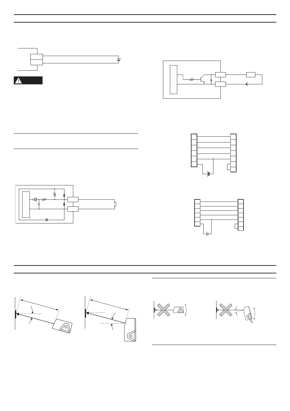
MOUNTING ANGLE AND POSITION OF THE BL-600 SERIES
Normally, the BL-600 Series provides the best reading stability when
mounted at the following angle and distance.
* The supplied mounting bracket facilitates the angle setting.
* The reading rate check mode ensures an optimal reading position.
Ö
Refer to User’s manual
* The laser beam application angle for the BL-650HA/651HA is 17° ±3°
with reference to a line perpendicular to the rear surface of the unit.
Note 1: Do not mount the BL-600 Series so that the laser beam is
applied to bar codes at a right angle (
±
10°). Otherwise, the specular
reflections may cause unstable reading or reading errors.
Note 2: The reading distance and angle may vary depending on the
narrow bar width, size, and printing quality of bar codes. Be sure to test
the BL-600 Series’ ability to read the actual bar codes in test mode.
5 V DC
BL-600
+5V
9
GND
5
+
GND
TIM
1
5
5 V DC
10 k
Ω
4.7
k
Ω
Internal circuit
BL-600
Contact or
solid-state
GND
OK/NG
4/6
5
Load
BL-600
10 k
Ω
* Rated load: 24 V DC
(30 mA) max.
+
Internal circuit
3
2
8
7
5
9
BL-600
SD
CS
RS
GND
+5V
PC
2
3
4
7
6
5
20
SD
RD
RD
RS
CS
SG
DR
ER
D-sub 25-pin (male)
M2.6 screw
D-sub 9-pin (male)
# 4-40 screw
2
3
7
8
5
9
PC
SD
RD
RS
CS
GND
+5V
3
2
8
7
5
4
6
SD
RD
CS
RS
SG
ER
DR
+
BL-600
D-sub 9-pin (female)
# 4-40 screw
D-sub 9-pin (male)
# 4-40 screw
Connecting the computer with 9-pin
Connecting the computer with 25-pin
BL-600/601/600HA/601HA
BL-650HA/651HA
Reading distance
15°
17°
Reading distance
Reading distance
BL-600/601: 120 mm
BL-600HA/601HA: 90 mm
Reading distance
BL-650HA/651HA: 65 mm
Within ±10°
Within ±10°
Incorrect
Incorrect
BL-600/601/600HA/601HA
BL-650HA/651HA