Part names and functions, Connection and wiring, Laser safety precautions – KEYENCE BL-600 Series User Manual
Page 2: Part names and functions connection and wiring
2
LASER SAFETY PRECAUTIONS
Follow the safety precautions below to ensure operator safety:
• Operate the BL-600 Series only according to the procedures
described in this instruction manual.
Otherwise, injury may occur due to exposure to the laser beam.
• Do not disassemble the sensor head.
Laser emission from the BL-600 series is not automatically stopped if
the sensor head is disassembled. If you disassemble the sensor head
for inspection or repair, you may be exposed to the laser beam.
If the BL-600 series malfunctions, contact KEYENCE immediately.
• Do not stare into the direct or specularly reflected beam.
Staring into the beam may result in serious eye injury.
• Protective enclosure
We recommend that you install a protective enclosure around the
sensor head to prevent any person from getting near the sensor head
during operation.
• Protective goggles
We recommend that you wear protective goggles when using the
BL-600 series.
• Stop laser emissions before cleaning the laser emission port.
Failure to stop the laser emission may expose eyes or skin to the laser
beam.
• Check the laser beam path.
To prevent exposure to the laser beam due to specular or diffuse
reflection, install a screen which offers the appropriate reflectance and
temperature characteristics to interrupt the reflected laser beam.
Do not install the BL-600 series in such a way that the laser beam
passes at eye height.
5. Safety Features Provided with the BL-600 Series
The BL-600 series is provided with the following safety features. Make
sure these features function correctly before operating.
• Laser emission caution LED (LASER ON LED)
During laser emission, the LASER ON LED illuminates. The LED ON
status can be checked through the laser protective glasses.
• Laser forced OFF command
Sending the laser forced OFF command to the BL-600 can inhibit
emission of laser beams. When working near the laser transmitter, be
sure to use the laser forced OFF command to avoid looking into the
laser beams.
When this command is selected, the bottom STABILITY LED flashes.
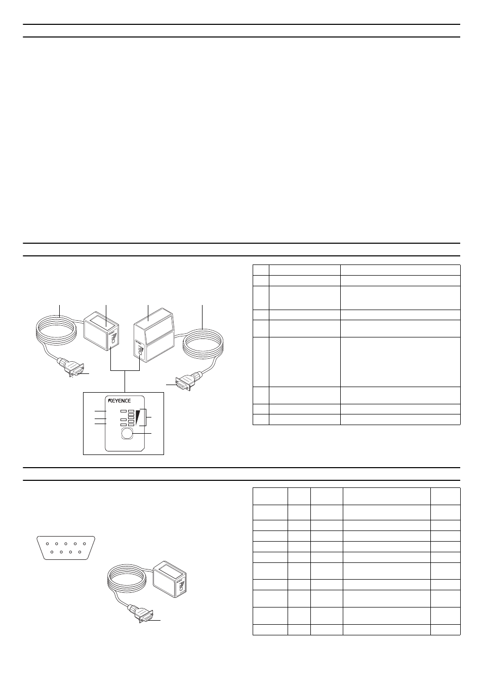
PART NAMES AND FUNCTIONS
CONNECTION AND WIRING
Pin assignment of the BL-600 Series power supply
connector
LAS
ER
ON
OK/NG
TIMING TES
T
BL
-60
0
LASE
R ON
OK/N
G
TIM
ING
TE
ST
BL-600
z
BL-600/601/600HA/601HA
z
BL-650HA/651HA
8
6
7
6
8
LASER ON
OK/NG
TIMING
TEST
BL-600
1
2
3
4
5
7
No.
Name
Function
1
LASER ON LED
Lit when laser beams are emitted.
2
OK/NG LED
• When OK output is ON: The green LED
lights.
• When NG output is ON: The red LED lights.
3
TIMING LED
Lit when trigger input is ON.
4
STABILITY LED
Displays the reading stability and the BL-600
operating status.
5
TEST SWITCH
This switch allows the following operations:
• Start the test mode.
• Pressing the switch once within two
minutes reads the bar code once.
• Sets the communication protocol to the
intival values when sending the settings.
• Reset the error status.
6
Transmitter/receiver
Window to emit laser beams and receive
reflected lights.
7
Power supply connector
Connected to the special power supply unit.
8
Cable
Cable length is 1.8 m.
LAS
ER
ON
OK/N
G
TIMING TES
T
4
5
3 2 1
9 8 7 6
Connector pin assignment
D-sub 9-pin (female)
#4-40 screw (male)
Power supply
Connector
Pin No.
Cable
color
Symbol
Description
Signal
direction
Connector
case
Shield
FG
Frame ground
---
1
Yellow
TIM
Trigger input
Input
2
Brown
RD (RXD)
Receives RS-232C data
Input
3
Purple
SD (TXD)
Sends RS-232C data
Output
4
White
OK
OK output
Output
5
Black
GND (SG)
Ground (Common ground for
respective signals)
---
6
Gray
NG
NG output
Output
7
Pink
RS (RTS)
Request to send RS-232C data
(always ON)
Output
8
Blue
CS (CTS)
Enable to send data through
RS232C
Input
9
Red
+5 V
+5 V DC power supply
Input