Dimensions – KEYENCE BL-1300 Series User Manual
Page 5
5
E BL-1300-IM
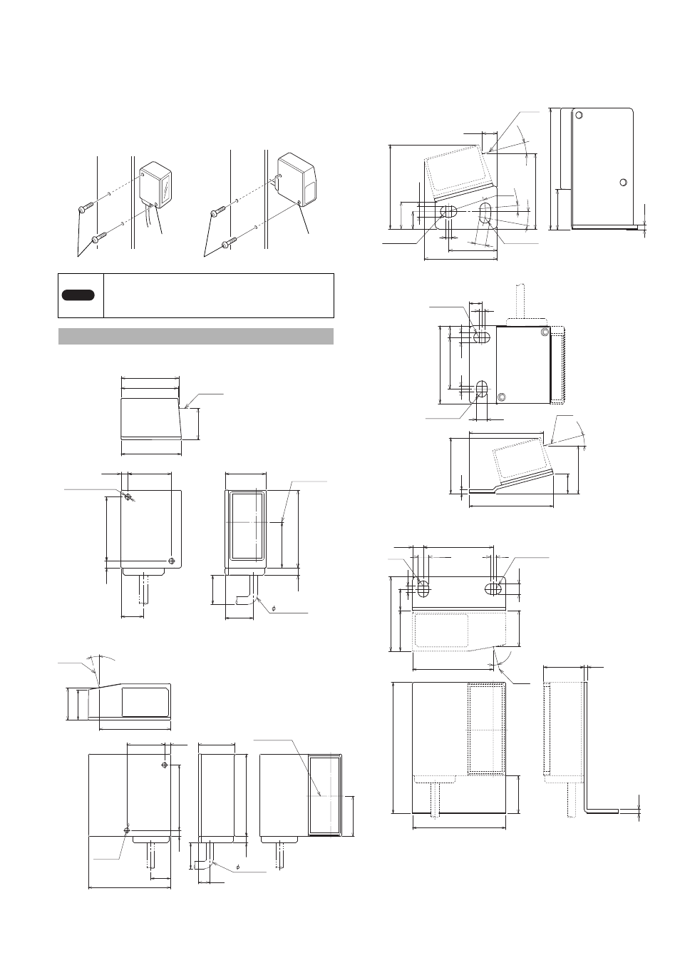
Mounting the BL-1300 Series without the mounting
bracket
1
Fasten the BL-1300 Series.
Fasten the BL-1300 Series in the mounting position with M3 screws.
* The M3 screws are not included. Select the M3 screws after checking
the panel thickness and other factors of the mounting position.
(The mounting hole for the BL-1300 Series is 4 mm deep.)
Main unit (BL-1300/1301/1300HA/1301HA/1370/1371)
Main unit (BL-1350HA/1351HA)
Mounting bracket
* On the bottom of the mounting bracket, an insulation sheet is attached.
Do not remove it.
•
For the front type
•
For the side type
Note
To suppress the influence of noise, mount the insulation
plate between the unit and the place it will be mounted. If
the insulation plate is not mounted, a reading error or an
incorrect reading may occur.
Dimensions
BL-1300/1301/1300HA/
1301HA/1370/1371
BL-1350HA/1351HA
Mounting screw (M3)
Mounting screw (M3)
Mounting
hole
Mounting
hole
4.2
29.75
22.5
3.5
33
3.5
11.5
14.55
21
31
29.33
40
3.8
15.95
23.46
Laser beam
2-M 3 Depth 4
Center of
scanning
15
mi
n.
Cable length: 1.8 m
4.2
18.66
48
11.5
3.5
38.1
6.45
21
22
3.5
17.6
48
3.8
41.56
23.47
15°
Laser
beam
2-M 3
Depth4
Cable length: 2 m
15 m
in.
Center of
scanning
25
7.82
43.35
2.2
59.6
19.6
3
5.5
5.5
9
14
37.6
38.65
2-R 2.75
R19
2-R 2.75
5°
10°
15°
2.2
40
6
26.5
35
.3
3
6.5
5.3
32.7
11.4
49.35
43.58
28.01
2-R 2.65
2-R 2.65
15
°
Mounting bracket A
Mounting bracket B
Laser
beam
Laser beam
18.66
2.2
1.6
21
19.6
67.6
48
21
3
11
38.5
5.3
5.3
5.5
36
3
41.56
2-R 2.65
2-R
2.65
15°