Part names and functions, Connection and wiring method, Connection connector pin layout – KEYENCE BL-1300 Series User Manual
Page 3: Connecting the power supply, Wiring in1/in2 input pins, Wiring out1/out2/out3/out4 output pins, Wiring rs-232c
3
E BL-1300-IM
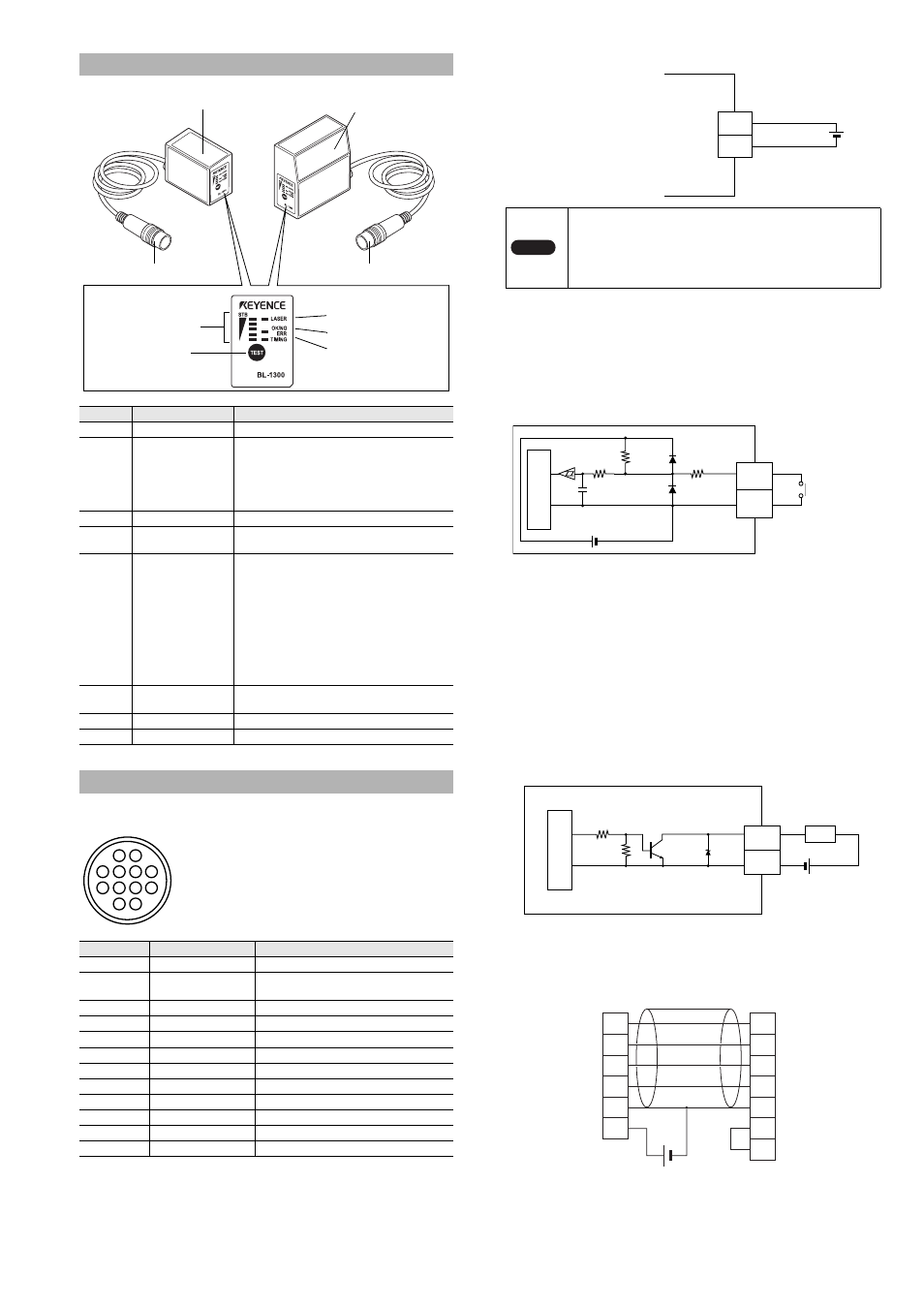
Connection connector pin layout
* The shield line is directly connected to the common GND.
Connecting the power supply
Connect a cable with a
length of 4.8 m or less.
Wiring IN1/IN2 input pins
•
The IN1 (timing) input is used to trigger the BL-1300 Series to read
barcodes (to emit a laser beam).
•
The IN2 (preset) input is used to trigger the BL-1300 Series to register
barcode data.
IN1/IN2 input is performed by no-voltage input.
Wiring OUT1/OUT2/OUT3/OUT4 output pins
•
OUT1 (OK) is used as output indicating that reading is successfully
completed and that the comparison and matching with preset data is
judged as OK.
•
OUT2 (NG/ERROR) is used as output indicating that reading has
failed and that the comparison and matching with preset data is judged
as NG.
•
OUT3 (ERROR) is used as output indicating that reading has failed.
•
OUT4(BUSY) is output any time the trigger input cannot be accepted,
such as cases where the BL-1300 Series is at initial start-up or in
setting mode, the motor/laser is damaged, the motor/laser is locked, or
the number of rotations of the motor is changed.
The output form of each signal is NPN open collector.
Wiring RS-232C
When connecting the BL-1300 Series to the PC, connect as shown
below.
Part Names and Functions
Number
Name
Function
1
LASER LED
Lit when laser beams are emitted.
2
OK/NG/ERR LED
• When OK output is ON: The green LED
lights.
• When NG output is ON: The orange LED
lights.
• When ERR output is ON: The red LED
lights.
3
TIMING LED
Lit when trigger input is ON.
4
STABILTY LED
Displays the reading stability and the BL-
1300 operating status.
5
TEST SWITCH
This switch is used to perform the following
operations.
• If this switch is pressed once shortly, a
barcode is read once.
• Starting and canceling the test mode
• Start reading of batch set bar codes
• Registering preset data
• Canceling PLC link errors
• Fixing the communication setting to the
initial value when setting transmission and
reception
6
Transmitter/receiver
Receives the emitted and reflected light of
laser beams and reads barcodes.
7
Connector
Used to connect to the communication unit.
8
Cable
Cable length is 2 m.
Connection and Wiring Method
Pin number
Symbol
Explanation
1
OUT1
Output pin 1 (initial value OK output)
2
OUT2
Output pin 2 (initial value NG/ERROR
output)
3
TXD
RS-232C transmission
4
CTS
RS-232C transmission permitted
5
OUT4
Output pin 4 (initial value BUSY output)
6
IN2
Input pin 2 (initial value PRESET input)
7
RXD
RS-232C reception
8
RTS
RS-232C reception permitted
9
OUT3
Output pin 3 (initial value ERROR output)
10
IN1
Input pin 1 (initial value TIMING input)
11
+5V
+5V power supply
12
GND (SG)
Common GND
6. Transmitter/receiver
7. Connector
8. Cable
8. Cable
1. LASER LED
2. OK/NG/ERR LED
3. TIMING LED
4. STABILITY LED
5. TEST SWITCH
6. Transmitter/receiver
7. Connector
6
10
5
9
4
2
1
8
12
11
3
7
Cable head cross-section view
RP17-13PA-12PC plug (male)
Manufactured by Hirose Electric Co., Ltd.
Note
• Reverse connection of the power supply is strictly
prohibited. This may cause product failure.
• Use a stable power supply of 5V DC
5%. Using a
power supply outside this range may cause product
failure.
GND
+5V
12
11
5 VDC
+
10 k
Ω
100
Ω
TIM
GND
12
6,10
4.7 k
Ω
5 VDC
In
te
rn
a
l ci
rc
u
it
Contact
or
non-contact
GND
OK/NG
12
+
1, 2,
5, 9
3.3 k
Ω
6.8 k
Ω
33 V
Load
* Rated load: 24V DC (30 mA) or less
In
te
rn
a
l ci
rc
u
it
BL-1300 Series
PC
3
4
7
8
11
12
TxD
CTS
RxD
RTS
GND
+5V
2
7
3
8
5
4
6
+
RxD (RD)
RTS (RS)
TxD (SD)
CTS (CS)
GND (SG)
DTR (ER)
DSR (DR)
Round
connector
12-pin (male)
D-sub9 pin
(female)
#4-40 screw