Installing the bl-1300 series, Mounting the bl-1300 series – KEYENCE BL-1300 Series User Manual
Page 4
4
E BL-1300-IM
When installing the BL-1300 Series, adjust the mounting angle and
distance as shown below.
Adjusting the mounting angle
Mount the BL-1300 Series so that a laser beam is applied at an angle of
approximately 15
.
For the front type of the BL-1300 Series BL-1300/1301/1300HA/1301HA/
1370/1371, the unit must be tilted at an angle of 15
.
For the side type BL-1350HA/1351HA, it is not necessary to tilt the unit
because a laser beam is emitted at an angle of 15
.
Adjusting the reading distance
The BL-1300 Series normally provides stable reading when it is mounted
at the following distance.
* The supplied mounting bracket facilitates the angle setting.
* The reading rate check mode ensures an optimal reading position.
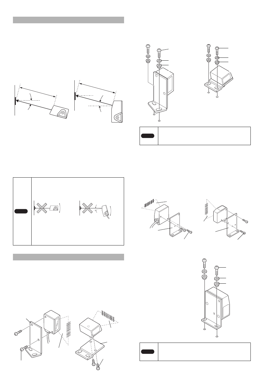
Attaching the front type BL-1300/1301/1300HA/1301HA/
1370/1371 to the mounting bracket.
The following procedure is for mounting the BL-1300 using the supplied
mounting bracket.
1
Attach the BL-1300 Series to the mounting bracket.
* Refer to page 5 for the dimensions of the mounting bracket.
2
Fasten the mounting bracket to the unit.
* Mounting screws (M4) are not included.
Attaching the side type BL-1350HA/1351HA to the
mounting bracket
The following is the procedure for mounting the BL-1350HA/1351HA
using the supplied mounting bracket.
1
Attach the BL-1300 Series to the mounting bracket.
* The mounting bracket for the BL-1300 allows two mounting orientations.
Choose the appropriate orientation according to the application.
* Refer to page 5 for the dimensions of the mounting bracket.
2
Fasten the mounting
bracket to the unit.
* Mounting screws (M4) are
not included.
Installing the BL-1300 Series
Model
Mounting distance
BL-1300/1301
:
120 mm
BL-1300HA/1301HA
:
90 mm
BL-1350HA/1351HA
:
65 mm
BL-1370/1371
:
230 mm
Note
• Do not mount the BL-1300 Series so that the laser
beam is applied to bar codes at a right angle (
10).
Otherwise, the specular reflections may cause
unstable reading or reading errors.
• The reading distance and angle may vary depending
on the narrow bar width, size, and printing quality of
bar codes. Be sure to test the BL-1300 Series' ability to
read the actual bar codes using "Reading rate check
mode".
Mounting the BL-1300 Series
Front type
BL-1300/1301/1300HA/
1301HA/1370/1371
Side type
BL-1350HA/1351HA
Reading distance
Reading distance
15
15
Within
10
Within
10
15
Front type
Side type
Incorrect
Incorrect
Supplied
mounting
screw (M3)
Mounting
bracket B
Laser
beam
When mounting bracket A is
used
Laser
beam
Mounting
bracket A
Supplied mounting
screw (M3)
When mounting bracket B is
used
Note
Be sure to mount the supplied insulation spacer to
suppress the influences of noises from the unit side.
If the insulation spacer is not mounted, there is risk of
the occurrence of a reading error or a wrong reading.
Note
Be sure to mount the supplied spacer to suppress the
influences of noise. A reading error or an incorrect error
reading may occur if the insulation spacer is not
mounted.
When mounting bracket A is used
Mounting screw
(M4)
Washer
Insulating
spacer
When mounting bracket B is
used
Mounting
screw (M4)
Washer
Insulating
spacer
Laser beam
Mounting
bracket
Supplied mounting
screw (M3)
Supplied mounting
screw (M3)
Mounting
bracket
Laser
beam
Mounting
bracket
Mounting
screw (M4)
Washer
Insulating
spacer