Connection and wiring method – KEYENCE SR-600 Series User Manual
Page 3
3
E SR-600-IM
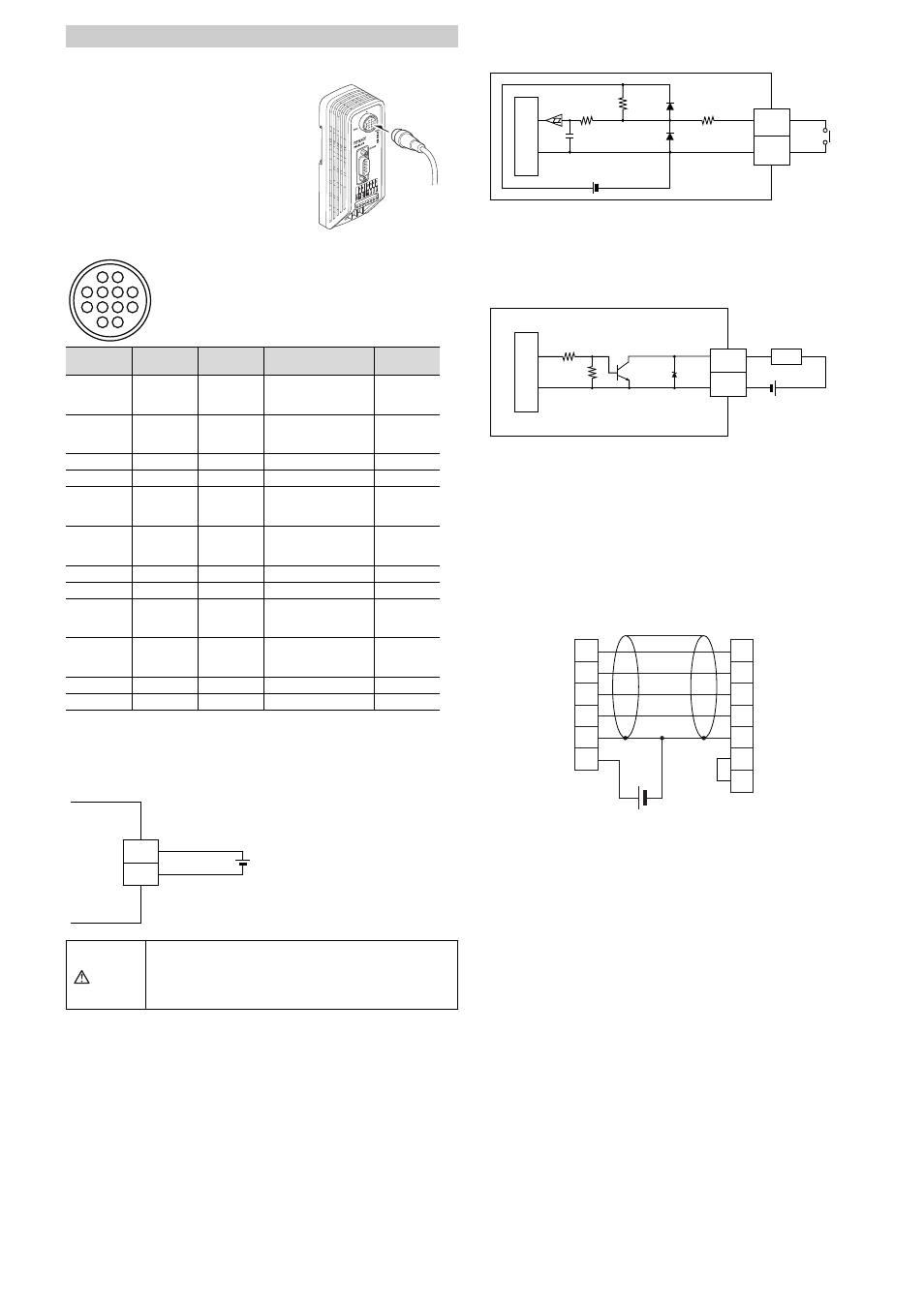
Connection to the communication unit
Connect the connector to the communication unit
(N-R2/UB/R4/L1).
Refer to the communication unit instruction manual
for more details.
Connector pin alignment
* The shielded wire is connected to a signal ground.
It is possible to change the functions of the input terminals and output terminals. Refer
to the user's manual for making these changes.
Connecting the power
Input terminal 1 and Input terminal 2 wiring
These are non-voltage inputs. Connect relay contacts or NPN open collector outputs.
•
The TIMING and PRESET inputs are non-voltage inputs.
•
TIMING (Input terminal 1) is input to initiate the 2D code and barcode reading.
•
PRESET (Input terminal 2) is input to preset (register) the 2D code and barcode data
on the SR-600 Series.
Output terminal 1, Output terminal 2, Output terminal 3 and
Output terminal 4 wiring
These are NPN open collector outputs.
•
OK (Output terminal 1) is output for a successful reading when a check against
preset data is successful.
•
NG/ERROR output (Output terminal 2) is output for an unsuccessful reading when a
check against preset data fails.
•
ERROR (Output terminal 3) is output for an unsuccessful reading.
•
BUSY (Output terminal 4) is output when preset data registration has been
completed and internal processing is taking place.
When BUSY is output, TIMING (Input terminal 1) cannot be input.
RS-232C wiring
Use the following wiring when connecting to a PC or a PLC.
Connection and Wiring Method
Pin no.
Wire color
Symbol name
Description
Signal
direction
1
Transparent
OUT1
Output terminal 1
(Default value:
OK output)
Output
2
Gray
OUT2
Output terminal 2
(Default value:
NG/ERROR output)
Output
3
Purple
TxD
RS-232C send
Output
4
Blue
CTS
RS-232C send OK
Input
5
Lt. blue
OUT4
Output terminal 4
(Default value:
BUSY output)
Output
6
Yellow green
IN2
Input terminal 2
(Default value:
PRESET input)
Input
7
Brown
RxD
RS-232C receive
Input
8
Pink
RTS
RS-232C receive OK
Output
9
Orange
OUT3
Output terminal 3
(Default value:
ERROR output)
Output
10
Yellow
IN1
Input terminal 1
(Default value:
TIMING input)
Input
11
Red
5 V
5 V Power
–
12
Black
GND (SG) Power GND/Signal GND
–
CAUTION
• Do not use a reverse connection for the power supply.
Doing so may damage the unit.
• Use a stable power supply that is 5 VDC +5%, -10%.
Using a power supply that exceeds this range may
damage the unit.
6
10
5
9
4
2
1
8
12
11
3
7
RP17-13PA-12PC plug (male)
Made by Hirose Electric Co., Ltd.
GND
+5V
12
+
11
5 VDC
10kΩ
220Ω
IN
GND
12
6,10
With or
without
contacts
4.7kΩ
DC5V
Internal circ
u
it
Internal circ
u
it
GND
OUT
12
+
1, 2,
5, 9
Load
* Rated load: 24VDC (30mA) or less
4.7kΩ
47kΩ
33V
RxD(RD)
RxD
RTS(RS)
RTS
TxD(SD)
TxD
SR-600 Series
DOS/V computer
D-sub 9-pin
(female)
#4-40 screw
Round
connector
12-pin
(male)
CTS(CS)
CTS
GND(SG)
GND
+5V
+
DTR(ER)
DSR(DR)
3
4
7
8
12
11
2
7
3
8
5
4
6