2 ion monitor functions, Ion monitor functions, 3 alarm output functions – KEYENCE SJ-M400 User Manual
Page 8: Alarm output functions, 4 other functions, Abnormal discharge detection function, Static elimination stop function, Air purge function, Other functions
8
3-2
Ion Monitor Functions
This section describes the ion monitor functions of the SJ-M Series.
Ion monitor functions are enabled in the Run mode.
Ion Monitor Functions
The charged level of the target object and the level of ions generated from the static elimination head
are indicated on the ion monitor.
The ion monitor indication can be switched by
.
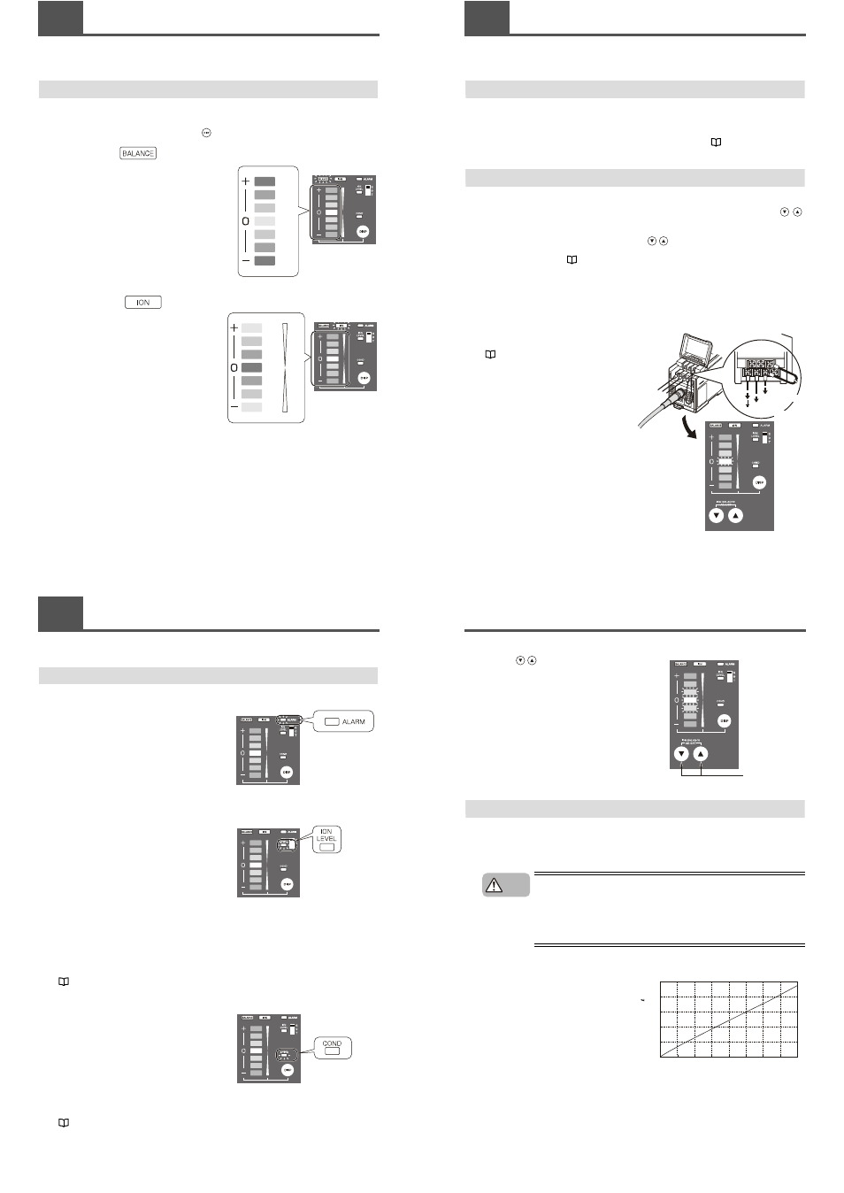
■ Charge monitor
This monitor indicates the charged and decharged
states of the target object.
The indication of this monitor fluctuates towards the
+ and – sides according to the charged level. The
further the indication is away from the center LED,
the larger the charged level. When static elimination
is completed, the indication returns to the center
LED so that you can easily tell how static
elimination is progressing.
The ion balance indicator lights when the charge
monitor is operating.
■ Ion level monitor
This monitor indicates the level of ions being
generated by the Static Elimination Head.
The level of plus ions being generated is indicated
on the upper side, while the level of minus ions is
indicated on the lower side. The further the
indication is away from the center LED, the larger
the level of ions. In a state where ions are being
sufficiently generated, both ends of this monitor light
(green).
The ion balance indicator lights when the ion level
monitor is operating.
Red
Orange
Orange
Green
Orange
Orange
Red
Green
Green
Orange
Red
Orange
Green
Green
Max.
+ ion
Min.
Min.
- ion
Max.
3-3
Alarm Output Functions
This section describes the alarm output functions of the SJ-M Series.
Alarm Output Functions
■ Alarm output function (ALARM)
The alarm indicator blinks (red) and an alarm signal
(control output (N.C.)) is output, for example, when
internal circuits are damaged or abnormal discharging
occurs. When an alarm signal is output, static
elimination is forcibly stopped.
Alarm output turns ON even in a static elimination
stopped state (including forced static elimination stop).
■ Ion level alarm output function (ION LEVEL)
The ion level alarm indicator lights and an alarm signal
(control output (N.O.)) is output when the level of
generated ions drops due to a dirty or worn electrode
probe, for example. When an alarm signal is output,
static elimination is not stopped.
Alarm output can be adjusted in three stages
according to the level of ions generated.
The default setting for the ion level alarm sensitivity
setting is Low.
The ion level alarm serves as a guideline for learning
when to perform maintenance on the electrode probe.
As static elimination is continued, be sure to turn the
power OFF before starting maintenance on the
electrode probe.
The ion level alarm output function is enabled in the
Run mode.
"Ion level alarm sensitivity setup" (page 7)
■ Condition alarm output function (COND)
The condition alarm output indicator lights and an
alarm signal (control output (N.O.)) is output when
static elimination performance is influenced by an
excessive charge on the target object. When an alarm
signal is output, static elimination is not stopped.
Alarm output can be adjusted in three stages
according to the installation environment. The default
setting for the condition alarm sensitivity setting is
Low.
The ion level alarm output function is enabled in the
Run mode.
"Condition alarm sensitivity setup" (page 7)
3-4
Other Functions
This section describes the abnormal discharge detection and static elimination stop functions of the SJ-
M Series.
Abnormal Discharge Detection Function
To prevent trouble, the generation of ions is stopped when abnormal discharging caused by
condensation on the electrode probe tips or adhesion of debris, for example, is detected. At this time,
the alarm indicator and ion monitor blink to inform you that an abnormality has occurred. For details of
the indicated state on the Controller Unit (operation/display section), see
"During an alarm (level
2)" (page 12).
Static Elimination Stop Function
You can turn off only static elimination while leaving the unit in a powered-on state by disconnecting the
trigger input and 0 V terminals on the Controller Unit (I/O terminal section), or by holding down
on the Controller Unit simultaneously (operation/display section) for about three seconds.
When static elimination stop input has been performed on the Controller Unit (operation/display
section), this state can be canceled by holding down
simultaneously for about three seconds.
For details on indication states on the Controller Unit (operation/display section) when static elimination
stop input is canceled, see
"Static elimination stop input (operation/display section)" (page 12).
■ Stopping static elimination
Static elimination is stopped by either of the following methods.
By operation on the Controller Unit (I/O terminal section):
Disconnect the trigger input and 0 V terminals
to stop static elimination.
The center LED of the ion monitor blinks (red).
"Controller Unit (I/O terminal section)" (page 4)
To 24 VDC
power supply
Remove the shorting bar.
To 24 VDC
power supply
3-4
Other Functions
By operation on the Controller Unit (operation/display section):
Hold down
simultaneously for about three
seconds to stop static elimination.
The three center LEDs of the ion monitor blink
(red).
Air Purge Function
Dirt can be prevented from sticking to the electrode probe by supplying clean or dry air from the air duct
of the static elimination head. This also extends the static elimination range.
* The pressure value at the neck of the air duct is indicated as the air pressure.
Use clean air or dry air of temperature –25°C, and of mesh size of about 0.01 μm.
• Be sure to limit the air pressure to 0.7 MPa. Exceeding this limit may cause
accidents or malfunction.
• Be sure to use clean air, dry air as the air for supplying to the Static
Elimination Head. Moisture or oil contained in the air or nitrogen may cause
discharge inside the Static Elimination Head, which may result in accidents
or malfunction.
■ Relationship between air press and flow rate
The figure on the right shows the relationship
between the flow rate and pressure of the
supplied air.
Select an air compressor having sufficient
flow rate capacity referring to this figure.
Hold down for
at least 3 seconds.
CAUTION
Air
su
pply flo
w
ra
te
( /
min
)
0
50
100
150
200
250
0
0.11
0.29
Air pressure (MPa)
0.01
0.19
0.39
0.49
0.56
0.70