3 list of options, List of options – KEYENCE SJ-M400 User Manual
Page 12
12
2
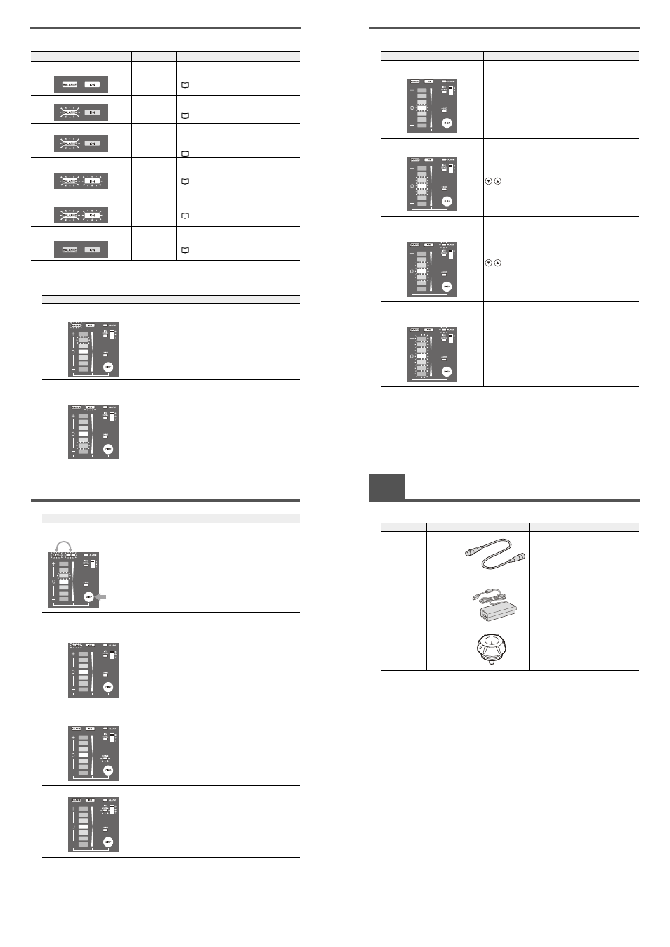
Table of Indicated States
■ Mode indications (except when the power is turned ON)
■ Indications in the Run mode
Lit State
Mode
Description
Either of the ion balance or ion level
indicators is lit.
Run mode
The SJ-M Series is operating in the Run mode. For
details on other indications, see the following.
"Indications in the Run mode"
The ion balance indicator is blinking.
Ion Balance
Manual
Adjustment mode
For details on other indications in the Ion Balance
Manual Adjustment mode, see the following.
"3. Adjusting ion balance" (page 7)
The ion balance indicator is blinking fast. End of ion
balance manual
adjustment (Run
mode)
The SJ-M Series is storing the setup information
after ion balance manual adjustment. Though the
SJ-M Series is operating in the Run mode, it cannot
enter the Select mode yet.
"3. Adjusting ion balance"(page 7)
The ion balance indicator and ion level
indicator blink alternately.
Select mode
For details on other indications in the Select mode,
see the following.
"2. Changing settings" (page 6)
The ion balance indicator and ion level
indicator blink alternately fast.
Setup mode
For details on other indications in the Setup mode,
see the following.
"2. Changing settings" (page 6)
Both the ion balance indicator and ion
level indicators are out.
Other
Static elimination is not being performed. For
details on other indications, see the following.
"Other indications" (page 12)
Lit State
Description
One of the ion monitor LEDs and the ion
balance indicator light (red).
Charged level indication
This indicates the charged level of the target object. When there
is a plus charged object, the LEDs on the upper side (+ side)
light, and when there is a minus charged object, the LEDs on the
lower side (– side) light according to the charged level.
One each of the plus and minus side
LEDs of the ion monitor, and the ion level
indicator light (red).
Ion level indication
This indicates the level of ions that are being generated by the
SJ-M Series.
2
Table of Indicated States
Charged level indication or ion level
indication
Display selection
The display switches to the charged level indication when (DISP)
is pressed while the ion level is indicated.
When the charged level is indicated, the display switches to the
ion level indication.
The ion balance indicator lights, and one
of the ion monitor LEDs blinks.
Ion balance manual setup confirmation
If the device is not in an ion balance manual setup state, you can
confirm the ion balance manual setup by pressing either of the
ion balance adjustment keys. During confirmation, the ion
monitor LEDs blink in one of the following three colors:
Orange: The LED blinks (orange) at the position corresponding
to the setup state when ion balance manual setup is
being performed. (Sometimes the center LED also is
lit.)
Red:
The LED at the edge of the side (+ or –) that was set
blinks (red) when the set value was set to MAX during
ion balance manual setup.
Green:
The center LED blinks (green) for the duration that the
ion balance adjustment key is held down when ion
balance manual setup is not being performed.
The condition alarm indicator lights (red).
Condition alarm
The condition alarm indicator lights (red) when the ion balance
has deteriorated influenced by the installation environment.
The ion level alarm indicator lights (red).
Ion level alarm
The ion level alarm indicator lights (red) when the generated ion
level falls below the preset level.
Lit State
Description
Hold down for
less than 1 second.
2
Table of Indicated States
■ Other indications
Lit State
Description
The center LED of the ion monitor blinks
(red).
Trigger input (I/O terminal section)
• In Spot mode
The center LED of the ion monitor blinks (red) when the trigger
input and 0V terminals are disconnected to stop static
elimination.
• In Gun mode
The state that was active before the power was turned OFF is
displayed.
The three center LEDs of the ion monitor
blink (red).
Static elimination stop input (operation/display section)
The three center LEDs of the ion monitor blink (red) when
are pressed and held down at the same time for about
three seconds to stop static elimination.
The alarm indicator and the three center
LEDs of the ion monitor blink (red)
simultaneously.
During an alarm (level 1)
The alarm indicator and the three center LEDs of the ion monitor
blink (red) simultaneously in the following instances.
Remedy the cause of the alarm, and simultaneously hold down
for about three seconds. This cancels the alarm state,
and executes the power ON sequence.
Probable causes of alarms
• Cables are disconnected or broken.
The alarm indicator and the seven ion
monitor LEDs of the ion monitor blink (red)
simultaneously.
During an alarm (level 2)
The alarm indicator and seven LEDs of the ion monitor blink (red)
simultaneously in the following instances.
Remedy the cause of the alarm, and turn the power ON again.
If this alarm frequently re-occurs, contact your agent.
Probable causes of alarms
• Abnormal discharge
• Internal circuit damage
3
List of Options
This appendix lists the various options available for the SJ-M.
Item
Model
Description
External Appearance
Extension cable
SJ-C3
The 3 m extension cable is used for
extending the connection between the
Controller Unit and the Static Eliminator Head
Unit.
(Up to 3 cables can be connected.)
AC adapter
SJ-U2
AC adapter
* For details of the AC cable, contact the
KEYENCE sales office in your district.
Electrode
replacement unit
for SJ-M040
OP-84383
Electrode Unit made of tungsten