1 timing charts, 2 specifications, Timing charts – KEYENCE SJ-M400 User Manual
Page 10: Specifications, Ion generation control timing chart, Input response timing chart, Static elimination head/controller unit, Ac adapter
10
5-1
Timing Charts
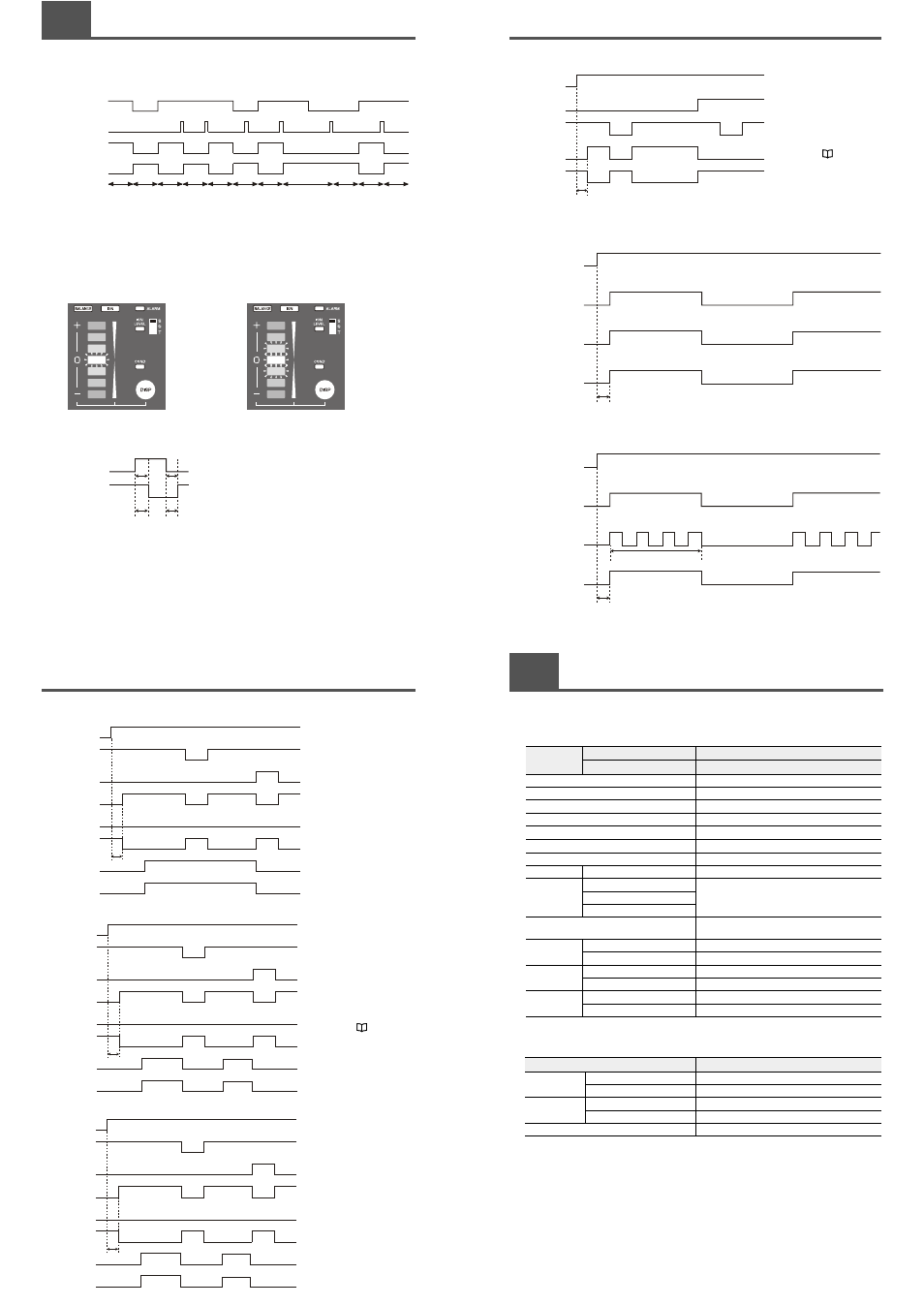
This section provides timing charts for SJ-M Series.
■ Ion generation control timing chart
Indicator states when static elimination is OFF
Normal static elimination OFF
• In Spot mode
The center LED of the ion monitor blinks (red).
• In Gun mode
The state that was active before the power
was turned OFF is displayed.
■ Input response timing chart
Normally ON Normally OFF Normally ON Forced OFF Normally ON Normally OFF Normally ON
Trigger input (terminal)
ON
OFF
Static elimination
stop input (controller)
ON
OFF
Ion emission state
Unit indicator
Emitting
No emissions
Alarm output
ON
OFF
Forced OFF
Forced OFF
Normally ON
Normally OFF
Max. 150 ms
Max. 150 ms
Static elimination
stop input (unit)
ON
OFF
Ion emission
state
Emitting
No emissions
Normal static elimination OFF
The three center LEDs of the ion monitor
blink (red).
5-1
Timing Charts
■ Ion level alarm output timing chart (GUN MODE)
■ Ion level alarm output timing chart (SPOT MODE)
■ Condition alarm output timing chart
MAX10 s
Power
ON
OFF
Trigger input (terminal)
ON
OFF
Static elimination
stop input (controller)
ON
OFF
Alarm indicator
ON
OFF
Alarm output (N.C.)
ON
OFF
Ion emission
Emitting
No emissions
Ion level indicator
ON
OFF
Condition/Ion level
alarm output (N.O.)
ON
OFF
Power
ON
OFF
Alarm indicator
ON
OFF
Alarm output (N.C.)
ON
OFF
Ion emission
Emitting
No emissions
Condition indicator
ON
OFF
Condition/Ion level
alarm output (N.O.)
ON
OFF
Trigger input (terminal)
ON
OFF
Static elimination
stop input (controller)
ON
OFF
MAX10 s
When the ion level alarm is output,
removing the cause of the alarm can
restore the normal state. One way of
restoring the normal state is to
perform maintenance on the electrode
probe.
For details on electrode probe
maintenance, see
"Performing
Maintenance on the Electrode
probe"(page 9).
Power
ON
OFF
Alarm indicator
ON
OFF
Alarm output (N.C.)
ON
OFF
Ion emission
Emitting
No emissions
Condition indicator
ON
OFF
Condition/Ion level
alarm output (N.O.)
ON
OFF
Trigger input (terminal)
ON
OFF
Static elimination
stop input (controller)
ON
OFF
MAX10 s
When the condition lalarm is output,
removing the cause of the alarm can
restore the normal state. One way of
restoring the normal state is to
improve the installation environment.
5-1
Timing Charts
■ Alarm output timing chart
■ Valve output timing chart
(1) When the valve control frequency is DC
(2) When the valve control frequency is other than DC
Power
ON
OFF
Trigger input
ON
OFF
Alarm indicator
Blinking
OFF
Alarm output (N.C.)
ON
OFF
Ion emission
Emitting
No emissions
MAX10 s
When the alarm is output, the normal
state can be restored by performing
one of the two available restore
methods depending on the cause of
alarm output.
For details on how to restore the
normal state, see "During an
alarm (level 2)" (page 12).
Power
ON
ON
OFF
Valve control
output
ON
OFF
Trigger input
terminal
OFF
ON
OFF
Ion emission
MAX10 s
The frequency and duty ratio
vary depending on the setting.
Power
ON
ON
OFF
Valve control
output
ON
OFF
Trigger input
terminal
OFF
ON
OFF
Ion emission
MAX10 s
5-2
Specifications
This section provides the specifications of the SJ-M400 Series.
■ Static Elimination Head/Controller Unit
*1 At a distance of 150 mm without using air purge.
■ AC Adapter
* The AC cable is for domestic use only (voltage rating 125 V).
Model
Controller Unit
SJ-M400
Static Elimination Head
SJ-M040
Voltage application method
Pulse AC
Applied voltage
±5.5 kV
Rated output voltage
±6 kV
Ion balance control method
I.C.C. method
Ion balance
±30 V or less
*1
Max. air pressure
0.7 MPa
Air supply tube
Outer diameter: 6 mm, Inner diameter: 4 mm
Control input
Trigger input
No-voltage input
Control output
Alarm output
NPN open collector
100 mA 40 V or less
Ion level/Condition alarm output
Valve control
Major functions
Condition alarm output, ion level alarm output, alarm
output, ion balance adjustment, air valve control
Rating
Power voltage
24 VDC ±10%
Current consumption
450 mA max.
Environmental
resistance
Operating ambient temperature
0 to +40°C
Operating ambient humidity
35 to +65%RH (condensation not allowed)
Weight
Static Elimination Head
Approx. 650 g
Controller Unit
Approx. 300 g
Model
SJ-U2
Rating
Rated input
100 to 240 VAC (50/60 Hz)
Rated output
24 VDC 2.65 A
Environmental
resistance
Operating ambient temperature
0 to +35°C
Operating ambient humidity
20 to 80% (condensation not allowed)
Weight
Approx. 250 g