2 connection and installation, Installing the sj-m series, Connecting cables – KEYENCE SJ-M400 User Manual
Page 5: Connection and installation
5
2-2
Connection and Installation
This section describes how to connect and install the Static Elimination Head and Controller Unit.
Installing the SJ-M Series
Install the SJ-M Series at locations where static electricity is generated or is likely to be generated.
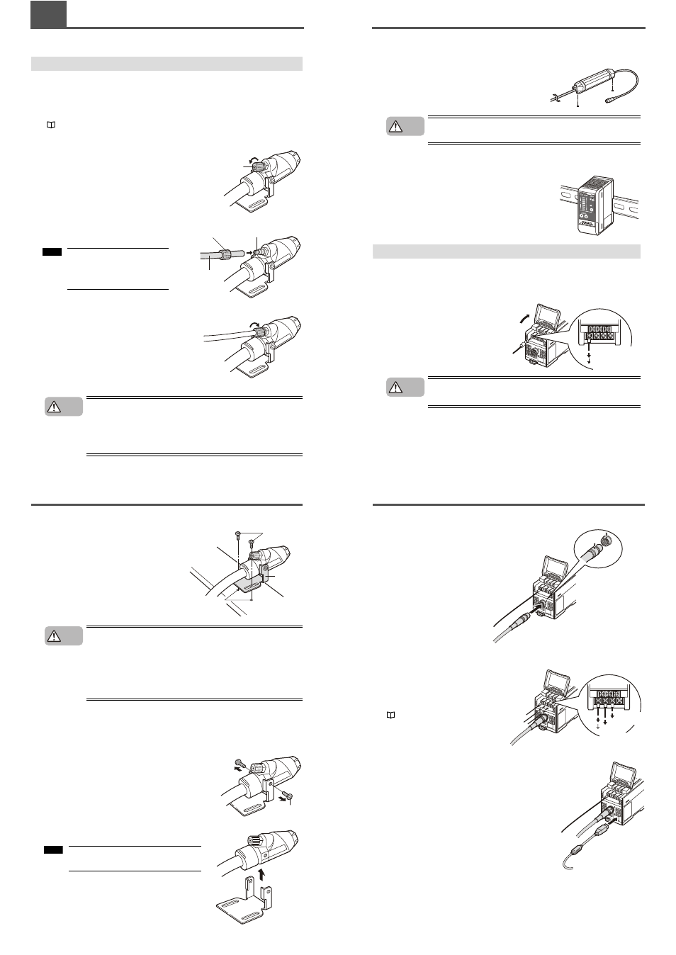
■ Installing the air supply tube
To use the air purge function, install an air supply tube to the air duct before securing the static
elimination head.
"Air Purge Function" (page 8)
1
Remove the tube fixing screw.
Turn the tube fixing screw attached at the air duct of
the static elimination head with your fingers to
remove it.
2
Connect the air supply tube to the air duct.
Pass the tube through the tube fixing screw and
then attach it completely to the air duct.
3
Secure the tube to the air duct with the tube fixing screw.
Tighten the tube fixing screw securely with your
fingers.
• Be sure to limit the air pressure to 0.7 MPa. Exceeding this limit may cause
accidents or malfunction.
• Be sure to use clean air, dry air as the air for supplying to the Static
Elimination Head. Moisture or oil contained in the air or nitrogen may cause
discharge inside the Static Elimination Head, which may result in accidents
or malfunction.
Tube fixing screw
Tube fixing screw
Tube
Air duct
Use Nylon or Urethane tube with a
6-mm outer diameter and 4-mm
inner diameter as the air supply
tube.
Note
CAUTION
2-2
Connection and Installation
■ Installing the Static Elimination Head
Adjust the angle of the static elimination head to
ensure proper installation. Tap M4 screw holes at
appropriate locations and secure the mounting
fixture with M4 screws.
When installing the SJ-M Series, observe the minimum bending radius of all
provided cables. Also, do not install the SJ-M Series with the cables deformed
by staples or other objects. Doing so might cause the SJ-M Series to
malfunction
When bending the cable frequently with the SJ-M Series in Gun mode, make
the cable's bending radius at least 5 times larger than the minimum bending
radius.
This value does not guarantee limitless number of bending times.
■ Detaching the mounting fixture from the head
The mounting fixture can be detached from the static elimination head.
1
Remove the M3 screws from the static elimination head.
Unscrew the M3 screws on both sides of the static
elimination head with a Phillips screwdriver to remove
them.
2
Detach the mounting fixture from the static elimination head.
M4 screws
Mounting
fixture
M4 tap
CAUTION
M3 screw
M3 screw
Keep the removed M3 screws and mounting
fixture safe so that they don't get lost.
Note
2-2
Connection and Installation
■ How to install the drive unit
Prepare mounting holes where the drive unit is being installed. Use M4 screws for installation.
(Tightening torque: 1 Nm or less)
The screws for installing the drive unit must be prepared
separately.
Make a space of 30 mm or more around the drive unit. Otherwise, the unit
may be damaged.
■ Installing the Controller unit
Mount the Controller Unit on the DIN rail.
Connecting Cables
When you have finished installing the Static Elimination Head, connect the ground lead, Static
Elimination Head connector cable and power supply.
■ Connecting the ground lead
Open the terminal plate cover on the Controller
Unit, and connect the ground lead to the GND
connection terminal.
Be sure to connect a Class D ground (maximum
resistance of 100 Ohms).
To prevent electric shock and to ensure accurate static elimination, be sure
to connect a Class D ground (maximum resistance of 100 Ohms).
M4 tap
CAUTION
Be sure to connect
a Class D ground
(maximum resistance
of 100 Ohms).
WARNING
2-2
Connection and Installation
■ Connecting the cable
Connect the Static Elimination Head
connector cable to the Controller Unit.
Connect this cable with the power
turned OFF.
When installing the Controller Unit
away from the Static Elimination
Head, use the optional extension
cable (SJ-C3). Up to 3 cables can be
connected.
■ Connecting the power supply
Connect the power supply according to either
of the following methods.
24 VDC power supply
Connect a 24 VDC output power supply having
sufficient power capacity margin to the power
terminals (terminals (5) and (6))
"Controller Unit (I/O terminal section)" (page 4)
AC adapter (SJ-U2)
Connect the AC adapter to the connector on the side of
the Controller Unit.
The AC adapter is available as an option.
Match and connect
the end of the connector
cable to the inlet on the
Controller Unit.
To 24 VDC
power supply
To 24 VDC
power supply