Precautions on regulations and standards, 1 features of the sj-m series, Outline of the sj-m series – KEYENCE SJ-M400 User Manual
Page 2: Features of the sj-m series
2
■
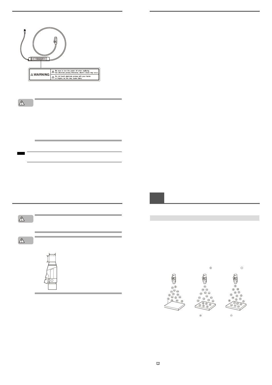
SJ-M Series Warning label
A WARNING label is affixed on the SJ-M Series to ensure safety. Read the description on this
WARNING label to ensure correct use of the SJ-M Series.
■
Installation Precautions
Avoid installing the SJ-M Series in the following locations as this may cause
accidents.
• Locations directly subject to vibration and shock
• Locations subject to ambient temperature outside of the 0°C to +40°C range
• Locations subject to ambient humidity outside of the 35 to 65%RH range
(condensation not allowed)
• Locations subject to sudden changes in temperature
• Locations subject directly to blasts from air conditioners
• Locations subject to volatile or flammable substance, solvents or corrosive
gases
• Locations subject to large amounts of dirt, and dust, salt, iron and oil smoke
• Locations that may be splashed with water, oil or chemical mist
• Locations where strong magnetic and electrical fields are generated
■
About Warm-up
After turning the SJ-M Series ON, leave it for about 20 minutes to allow the ion
balance to stabilize.
WARNING labels in Japanese, German, French, Italian and Chinese (Simplified) are provided.
Use them as necessary.
CAUTION
Note
■
Other Precautions
• Be sure to read the WARNINGS and CAUTIONS described in each of the
items in this Instruction Manual.
• This Static Eliminator has a built-in EEPROM. Do not turn the Static
Eliminator OFF during the setup.
Install the tip of the SJ-M040 paying attention to the following point.
●
Install the Static Elimination Head away from the wall or surrounding
objects.
CAUTION
CAUTION
20 mm or more
10 mm
or more
Precautions on Regulations and Standards
■
CE Marking
Keyence Corporation has confirmed that this product complies with the essential requirements of the
applicable EC Directive, based on the following specifications.
Be sure to consider the following specifications when using this product in the Member State of
European Union.
● EMC Directive(2004/108/EC)
• Applicable standard EMI: EN61326-1 (evaluated according to EN55011 Group 1, Class A)
EMS: EN61326-1
• Be sure to provide a ground when installing the SJ-M.
• The length of cable (power lead and I/O leads) must be less than or equal to 30m.
• Attach a one-loop ferrite core onto the High-voltage Cable Unit and pass the connector cable once
through the core.
• The following ferrite core is recommended:
SFC-10 made by KITAGAWA INDUSTRIES CO,LTD.
Remarks:
These specifications do not give any guarantee that the end-product with this product incorporated
complies with the essential requirements of EMC Directive. The manufacturer of the end-product is
solely responsible for the compliance on the end-product itself according to EMC Directive.
● Low-Voltage Directive (2006/95/EC)
• Applicable standard:
EN61010-1
• Overvoltage category
I
• Use this product under pollution degree 2.
• Use the power supply for the SJ-M Series, that satisfies the requirements of the Limited Power
Source specifications stipulated in EN60950-1 and certified by European third-party certification
organization, or a Keyence Corporation AC adapter (SJ-U2). The specifications of the AC adapter
(SJ-U2) are as follows.
When connecting to an SJ-U2, be sure to use a power cable compliant with European standards.
Applicable standard:
EN60950-1
Overvoltage category
II
Pollution degree
2
• Be sure to provide a ground when installing the SJ-M Series.
1-1
Features of the SJ-M Series
This section describes an outline of the functions, the features of the SJ-M Series.
Outline of the SJ-M Series
■ Pulse AC method
The SJ-M Series uses a pulse AC method that generates + and – charged air ions from a single
electrode probe. This system ensures a maximum ion level per unit time, which in turn high-speed static
elimination. The SJ-M Series also automatically controls the level of + and – ions generated matched to
the charged state of the target object. This enables high-speed and high-precision static elimination
suited to installation conditions.
■ I.C.C. (Ion Current Control) method
This control method calculates the charged level of the target object by sensing the state of ion current
that arises due to the potential difference between the electrode on the Static Elimination Head and
GND. Optimum static elimination matched to the state of the target object can be performed by rapidly
supplying the optimum ions suited to the polarity and charged level of the target object.
■ Ion monitor functions
●
Charge monitor
The integrated ion monitor allows you to learn how much the target object is charged by + or – ions.
This monitor also allows you to confirm at a glance how static elimination is being performed.
●
Ion level monitor
The ion level currently being generated by the Static Elimination Head is monitored at all times so that
drops in the generated ion level can be diagnosed on the unit. The generated ion level is indicated by
LEDs and an alarm can be output when the generated ions fall below a certain level. This allows you to
monitor the influence of a dirty electrode probe in advance.
"Ion Monitor Functions" (page 8)
Regular state
Target object in
non-charged state
Elimination of ions
from target object
Elimination of ions
from target object
Target object
charged
Target object
charged