3 external dimensions, 1 troubleshooting, 2 table of indicated states – KEYENCE SJ-M400 User Manual
Page 11: External dimensions, Troubleshooting, Table of indicated states
11
5-3
External Dimensions
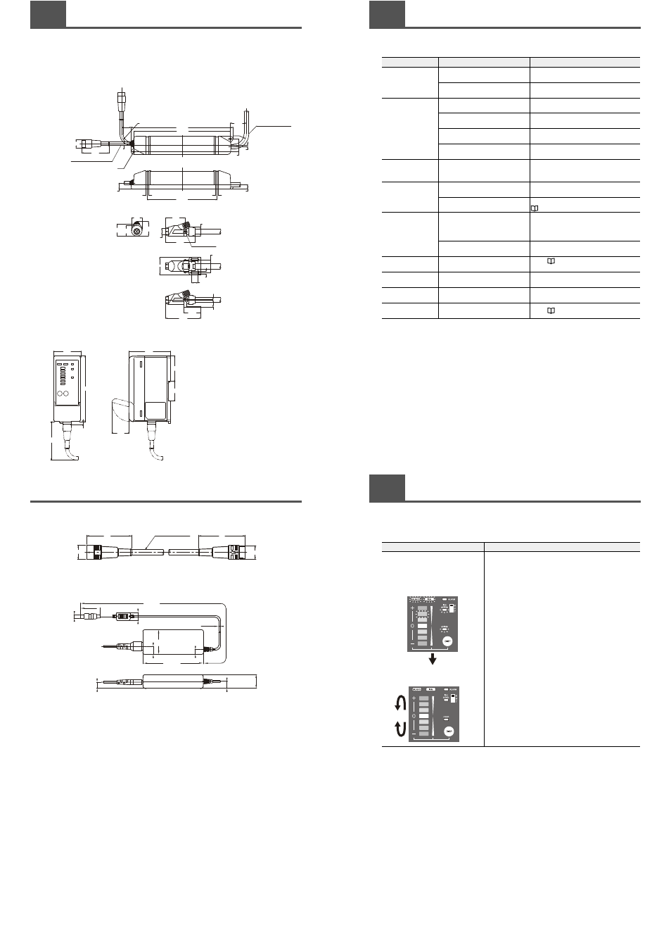
This section presents the external dimensions of the SJ-M Series.
■ Body
Static Elimination Head
Controller Unit SJ-M400
To the head part
(Drive part)
(Head part)
Cable length: 300 mm
φ6
51
3
18
191
181
24
30
2.5
R30
Cable length: 1.8 m
φ10
5
5
131
11.5
8.5
φ20
23
20
27
φ12
37
56
17
M3 screw
24
33
12
4.4
R18
φ15
2-
φ4.4
1
3
.5
1.5
32
66
SJ-M040
5
70
120
32
36
46
76
50
5-3
External Dimensions
■ Extension cable (SJ-C3)
■ AC adapter (SJ-U2)
* For details of the AC cable, contact the KEYENCE sales office in your district.
6 mm dia.
cable length 3 m
49
φ15.5
51
φ15
(37.5)
7
φ
1
6
(10.3)
(1
6
.3
)
(1
2
.5)
(1
4
)
2
8
φ
3.5
1800
11
4
.5
50.5
1
Troubleshooting
This appendix describes trouble that may occur during use of the SJ-M Series and how to remedy this
trouble. Check the following table before sending in your SJ-M Series for repair.
Symptom
Check Item
Remedy
No indication on ion
monitor
Is the power cable connected
properly?
Connect the power cable correctly.
Is a power supply within specification
being used?
Use a power supply that is within
specification.
Static elimination is
not performed.
Is the electrode probe worn or dirty?
Perform maintenance on the electrode probe
or replace the Electrode Unit.
Is static elimination stop currently
set?
Cancel the static elimination stop setting on
the SJ-M Series.
Is the abnormal discharge detection
function operating?
Check the Electrode Unit for any conductive
substances (e.g. oil droplets).
Is the trigger input terminal
disconnected?
Short the terminals (3) and (6).
Static elimination is
not performed
properly.
Are conductors or other Static
Eliminators located nearby the Static
Eliminator?
Move the Static Eliminator away from
conductors or other static eliminators nearby.
The ion level alarm is
indicated/output
Is the electrode probe worn or dirty?
Perform maintenance on the electrode
probes or replace the Electrode Unit.
Are conductive objects located in the
surrounding area?
Check the installation state.
"Installation site"(page 4)
The condition alarm is
indicated/output.
Are static elimination target objects
having a very high charged level
located nearby the Static
Eliminators?
Increase the number of connected static
eliminators.
Is the electrode probe worn or dirty?
Perform maintenance on the electrode
probes or replace the Electrode Unit.
The alarm indicator
lights.
–
Check "During an alarm (levels 1, 2)"
(page 12).
Control output is not
output correctly.
Is output wired correctly?
Check the output circuit and wiring, and
connect correctly.
The trigger input is not
input correctly.
Is input wired correctly?
Check the input circuit and wiring, and
connect correctly.
Do not know meaning
of indicators.
–
Check "Table
of
Indicated States".
2
Table of Indicated States
This appendix describes the various indicated states of the SJ-M Series.
■ Indicated states when the power is turned ON
Lit State
Description
The state (charged level indication or ion
level indication) that was active before the
power was turned OFF is displayed.
At the same time, the alarm indicator, ion
level alarm indicator, and condition alarm
indicator light (red).
The ion monitor LEDs fluctuate upward
and downward.
When the power is turned ON, the indicated state (charged level
indication or ion level indication) that was active before the power
was turned OFF is displayed. Also, the alarm indicator, ion level
alarm indicator and condition alarm indicator light (red) at the
same time. After this indication state continues for about two
seconds, the ion monitor LEDs fluctuate upward and downward,
and static elimination is then started. After static elimination
starts, the charged level or ion level is indicated.