Controller unit (i/o terminal section), 1 before installation, About static elimination performance – KEYENCE SJ-M400 User Manual
Page 4: Installation precautions, Before installation
4
1-3
Names and Functions of Parts
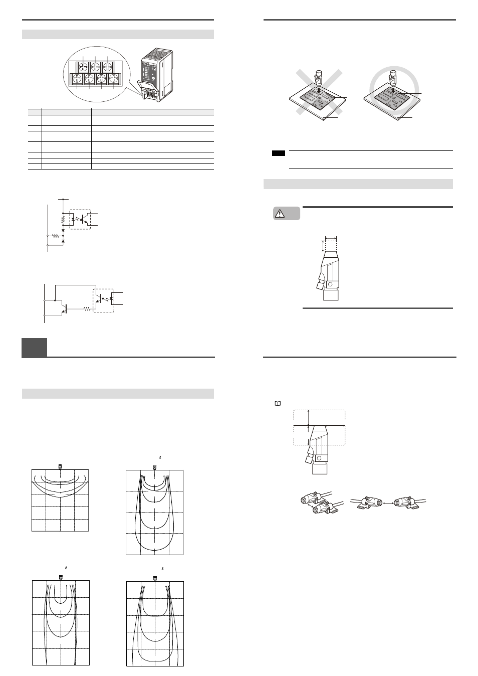
Controller Unit (I/O terminal section)
■ Input circuit diagram
■ Output circuit diagram
Number
Name
Function
(1)
Condition/ion level alarm
output terminal
Outputs when static elimination performance is influenced by an
unstable operating environment or when the ion emission level drops.
(2)
Valve output terminal
Outputs the ON/OFF signal for the valve.
(3)
Trigger input terminal
Static elimination can be turned ON/OFF by shorting this terminal with
(6).
(4)
Ground terminal
Be sure to connect a Class D ground (maximum resistance of 100
Ohms).
(5)
DC power terminal
24 VDC ±10%
(6)
0V terminal
0V for power and 0V for I/O
(7)
Alarm output terminal
Outputs when an alarm occurs. (N.C.)
(1)
(4)
(5)
(6)
(7)
(2)
(3)
+24V
3k
Ω
INPUT (3)
0V (6)
Input a no-voltage contact (relay, etc.)
or NPN open collector to INPUT and 0V.
[ (3) (trigger input)]
OUT
DC40V
100mA
0V (6)
Open collector output
[ (2) (valve output), (1) (condition/ion level alarm output), (7) (alarm output)]
2-1
Before Installation
This section describes the static elimination performance of the SJ-M400 Series.
Before you install the SJ-M400 Series, fully calculate the distance between the Static Elimination Head
up to the target object and the time required for static elimination.
About Static Elimination Performance
The following shows a typical example where static is eliminated from an aluminum plate (20 pF) 150 x
150 mm square charged to +1000 V by the SJ-M400 Series.
■ Static elimination area
The following graphs show the relationship between the time required for eliminating static from a target
object charged between +1000 to +100 V and the distance from the charged object up to the Static
Elimination Head.
No air
50
100
150
100
50 100 150
1.0 sec
200 mm
200 mm
200
300
400
500 mm
0.5 sec
5.0 sec
10 sec
23 Hz Air flow rate 20 N /min (pressure 0.06 MPa)
50
100
150
50 100 150 200 mm
200 mm
200
400
600
800 mm
0.5 sec
5.0 sec
2.0 sec
10 sec
1.0 sec
23 Hz Air flow rate 60 N /min (pressure 0.18 MPa)
50
100
150
50 100 150 200 mm
200 mm
200
400
600
800
1000 mm
0.5 sec
2.0 sec
1.0 sec
5.0 sec
23 Hz Air flow rate 230 N /min (pressure 0.7 MPa)
50
100
150
50 100 150 200 mm
200 mm
200
400
600
800
1000 mm
0.5 sec
2.0 sec
1.0 sec
5.0 sec
2-1
Before Installation
■ Appropriate static elimination method
Pay attention to the following points to ensure that static elimination is performed appropriately.
Static elimination cannot be performed accurately at locations where the target object is
touching a metallic body (grounded body).
Eliminate static from the target object at locations where it is not directly touching metallic bodied
(grounded body).
Static will be eliminated from only the surface of the insulated body (board, etc.) that is facing
the Static Elimination Head.
When eliminating static from both sides of a target object, install two SJ-M Series as one SJ-M Series
must be installed on either side of the target object.
Install the Static Elimination Head so that it can be easily accessed, for example, for
replacement of parts and cleaning.
Installation Precautions
■ Installation site
Install the tip of the SJ-M040 paying attention to the following point.
●
Install the Static Elimination Head away from the wall or surrounding
objects.
Insulating mat
Metal
Board
Board
Note
CAUTION
20 mm or more
10 mm
or more
2-1
Before Installation
■ Interference
The Static Elimination Head may not function properly if there is a conductor (grounded body) located
nearby or if two or more units are used close to each other. In such an installation, refer to the figure
below and maintain the indicated distance between the conductor (grounded body). If a conductor
(grounded body) is located inside the distances indicated below, adjust using the ion balance manual
setup.
"3. Adjusting ion balance" (page 7)
When two SJ-M Series units are used, refer to the figures below, and install the units so that the
following distances are maintained between the two Static Elimination Heads.
70 mm or more
100 mm or more
100 mm or more
100 mm or more
150 mm or more
150 mm or more