1 flow of operation, 2 list of setup and display functions, Controller unit – KEYENCE SJ-F300 Series User Manual
Page 7: Static elimination blower unit, 3 operation, Operation of power supply, Starting static elimination, Flow of operation, List of setup and display functions, Operation
6
3FUNCTION AND OPERATION
3-1
Flow of Operation
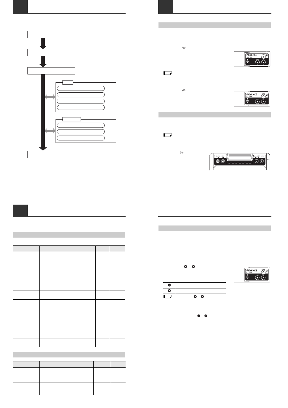
The following chart shows the operational flow from installing the SJ-F300 Series, connecting cables to
starting/stopping static elimination of the target object.
Conduct connection and installation
Page 4
Turn on the power
Page 6
Start static elimination
Page 6
Turn off static elimination
Page 8
Adjusting blow rate of the Static Elimination Blower Unit
Page 6
Adjusting sensitivity of ion level alarm
Adjusting sensitivity of condition alarm
Adjusting ion balance
Page 7
Page 7
Page 7
Setup
Confirming charged state and static eliminated state
Confirming ion level
Confirming blow rate of the Static Elimination Blower Unit
Page 8
Page 8
Page 8
Confirmation
3-2
List of Setup and Display Functions
This section describes the setup and display functions of the Controller Unit and the Static Elimination
Blower Unit of the SJ-F300 Series.
Controller Unit
Static Elimination Blower Unit
* In the startup of the second time or later, the state when the power turned off is in memory.
Function name
Description
Default
Page to
refer to
Power
Turns ON or OFF the main power supply. Collectively
controls the power supplies of the Static Elimination
Blower Units being in connection.
6
Collective blow rate
adjustment
Increases or decreases the blow rate of the blower.
Collectively adjusts the blow rates of the Static
Elimination Blower Units being in connection.
MIN
6
Alarm output
Blinks the indicator and outputs an alarm signal (N.C.)
when trouble occurs.
8
Ion level alarm output
Blinks the indicator and outputs an alarm signal (N.O.)
when the ion emission level drops below the setting
value. When such trouble occurs even in one of the
Static Elimination Blower Units being in connection,
blinks the indicator and outputs an alarm signal (N.O.).
8
Ion level alarm sensitivity
Alarm sensitivity can be adjusted in three stages. The
same setting is applied to all the Static Elimination
Blower Units being in connection.
Low
7
Condition alarm output
Blinks the indicator and outputs an alarm signal (N.O.)
when static elimination performance is influenced by the
installation environment or surrounding metal objects.
When such trouble occurs even in one of the Static
Elimination Blower Units being in connection, blinks the
indicator and outputs an alarm signal (N.O.).
9
Condition alarm
sensitivity
Alarm sensitivity can be adjusted in three stages. The
same setting is applied to all the Static Elimination
Blower Units being in connection.
Low
7
Abnormal discharge
detection
Stops the operation of static elimination and executes
alarm output when abnormal discharge is detected.
9
Collective ion balance
adjustment
Collectively adjusts the ion balances of the Static
Elimination Blower Units being in connection.
0 V
7
Static elimination stop
input
Stops the operation of static elimination of all the Static
Elimination Blower Units being in connection through
terminal input.
8
Function name
Description
Default
Page to
refer to
Individual start/stop of
static elimination
Starts or stops ion emission and fan rotation.
ON *
6, 8
Monitor
Displays the charge monitor (charged state and static
eliminated state of the target object), ion level (emitted
ion amount), and blow rate.
Charge monitor 8
Individual adjustment of
ion balance
Adjusts the balance of ions emitted from the Static
Elimination Blower Unit.
0 V
8
Individual adjustment of
blow rate
Adjusts the blow rate of the Static Elimination Blower
Unit.
MIN
7
3-3
Operation
Operation of Power Supply
This section describes how to operate the power supply of the Controller Unit and the Static Elimination
Blower Unit.
■ Turning on the power
Press and hold
on the Controller Unit for about two
seconds, then the power indicator lights in green and the
power for the Controller Unit and the Static Elimination Blower
Unit is turned on.
• In the default setting, turning on the power starts static elimination automatically.
• Connecting (supplying) the power starts static elimination automatically.
■ Turning off the power
Press and hold
on the Controller Unit for about two
seconds, then the power for the Controller Unit and the Static
Elimination Blower Unit is turned off.
Starting Static Elimination
Turning on the power of the fan of the Static Elimination Blower Unit and applying voltage to the
electrode needles generates ions to start static elimination. This section describes how to start static
elimination.
In the default setting, turning on the power starts static elimination automatically.
If static elimination is stopped before turning off the power in the initial use of this product,
turning on the power next time will not start static elimination automatically.
■ Starting static elimination
Press and hold
on the Static
Elimination Blower Unit for about two
seconds, then static elimination starts.
Power indicator
Tip
Tip
3-3
Operation
Adjusting Blow Rate of the Static Elimination Blower Unit
This blow rate adjustment enables static elimination from a wider area.
Follow one of the procedures below to adjust the blow rate of the Static Elimination Blower Unit.
• Blow rate adjustment using the Controller Unit
• Blow rate adjustment using the Static Elimination Blower Unit
This section describes each adjustment procedure.
■ Blow rate adjustment using the Controller Unit
Every pressing of
or
for one second increases or
decreases blow rate by one stage.
* Blow rates of all the Static Elimination Blower Units being
connected at the same time are increased or decreased
collectively (Collective adjustment of blow rate).
• Every pressing of
or
for about one second increases or decreases blow rate by one
stage.
• When two or more Static Elimination Blower Units having different blow rates used in
connection, the blow rates increase or decrease with the difference maintained. Note that
when the blow rate reaches a maximum or minimum value, the blow rate will be the same at
that value.
• Pressing and holding
or
enables continuous adjustment of blow rate.
Increases blow rate.
Decreases blow rate.
Tip