1 troubleshooting, 2 table of indicated states, Troubleshooting – KEYENCE SJ-F300 Series User Manual
Page 13: Table of indicated states, Aappendices
12
AAPPENDICES
1
Troubleshooting
This appendix describes troubles that may occur during the use of this product and troubleshooting
methods. Check the following table before sending in your SJ-F300 Series for repair.
Symptom
Check Item
Remedy
Are the power cable and the
extension cable connected properly?
Is a power supply within specification
being used?
Is the power turned off?
Is there sufficient power capacity?
Is static elimination turned off?
Are the electrode needles worn or dirty?
Is static elimination stop currently set?
Is the abnormal discharge detection
function operating?
Are conductors or other Static Elimination Blower
Units located near the Static Elimination Blower Unit?
Is the blow rate adjustment setting
set to low?
Is the filter on the back panel of the
blower clogged?
Are the electrode needles worn or dirty?
Are conductive objects located in the area
within 50 mm in front of the electrode needles?
Are conductors or other Static Elimination Blower
Units located near the Static Elimination Blower Unit?
Are the electrode needles worn or dirty?
-
Is wiring correct?
Is wiring correct?
Connect the power cable and the
extension cable correctly.
Use a power supply that is within
specification.
Refer to "1-3 Names and Functions of
Parts" ( page 3) of this manual.
The number of blower unit that the optional AC
adapter (SJ-U2) can drive is only one. If you attempt
to use two or more blower units in connection, use a
DC power supply with sufficient capacity.
Turn on static elimination by following the instructions of
"Starting Static Elimination" ( page 6) of this manual.
Perform maintenance on the electrode
needles or replace the electrode unit.
Cancel the static elimination stop input
of the SJ-F300 Series.
Check the electrode unit for any
conductive substances (e.g. oil droplets).
Keep the Static Elimination Blower Unit away from
conductors or other Static Elimination Blower Units.
Refer to the "Adjusting Blow Rate of the Static
Elimination Blower Unit" ( page 6) of this manual.
Clean the clogging duct and refuse off
the filter.
Perform maintenance on the electrode
needles or replace the electrode unit.
Keep the conductive objects away from the area
within 50 mm in front of the electrode needles.
Keep the Static Elimination Blower Unit away from
conductors or other Static Elimination Blower Units.
Perform maintenance on the electrode
needles or replace the electrode unit.
Refer to "During an alarm (levels 1, 2)"
( page 13) of this manual.
Check the output circuit and wiring,
and connect correctly.
Check the input circuit and wiring, and
connect correctly.
Monitor LEDs or
indicators are not
lit.
Power will not be
turned on.
Power is turned on but
the fan will not rotate.
Static is not
eliminated.
Static elimination is not
performed properly.
The blow rate is
reduced.
The ion level
alarm is output or
displayed.
The condition
alarm is output or
indicated.
The alarm
indicator lights up.
Control output is
not output correctly.
Static elimination stop
input is not input correctly.
2
Table of Indicated States
This appendix describes the various indicated states of the SJ-F300 Series.
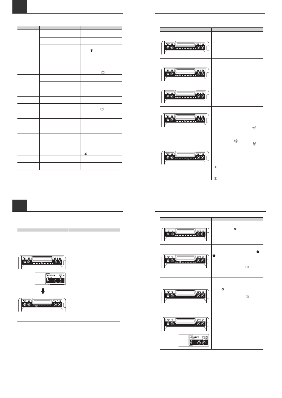
■ Indicated states when the power is turned ON
Lit State
Description
After the power indicator lit in green and the center
LED of the monitor lit in red, and then the monitor
LEDs light from side to side, static elimination is
performed. The state (charge monitor, ion level
monitor or blow rate setup monitor) that was active
before the power was turned OFF is displayed.
After the power indicator lit in green and the
center LED of the monitor lit in red, and then the
monitor LEDs light from side to side, the state
(charge monitor, ion level monitor or blow rate
setup monitor) that was active before the power
was turned OFF is displayed.
2
Table of Indicated States
■ Indicated states during setting change, confirmation and operation
(excluding when the power is turned ON)
Two monitor LEDs on the + side and - side,
respectively, and the ion level indicator light in red.
One monitor LED and the blow rate indicator light in red.
Ion level monitor display
This displays the amount of ions that are being
emitted by the SJ-F300 Series.
This displays the setting value of the blow rate of
the Static Elimination Blower Unit.
The center LED of the monitor lights in red.
Static elimination stop input (I/O terminal section)
The center LED of the monitor lights in red when
static elimination is turned off by shorting the static
elimination stop input terminal and the 0 V terminal.
Static elimination stop input (Blower section)
The center LED of the monitor lights in red when
static elimination is stopped by pressing for
about two seconds.
One monitor LED and the ion balance indicator
light in red.
Charge monitor display
This displays the charged level of the target
object. When there is a plus charged object, the
LED on the + side lights, and when there is a
minus charged object, the LED on the - side lights
to indicate the charged level.
The state (charge monitor, ion level monitor or
blow rate setup monitor) that was active before
static elimination was turned OFF is displayed.
Static elimination stop input canceling
(Operation/Display section)
Pressing and holding for about two seconds
after static elimination is turned off using
cancels the static elimination stop input. The state
(charge monitor, ion level monitor or blow rate
setup monitor) that was active before the static
elimination was stopped is restored.
Note that when an alarm condition occurs, the
LED blinks to indicate the cause of the alarm.
Refer to "Turning Off Static Elimination"
( page 8) for details about how to conduct
static elimination stop input from the Controller
Unit (Operation/Display section).
Refer to "During an alarm (levels 1, 2)"
( page 13) for indicated states during an alarm.
Lit State
Description
2
Table of Indicated States
Lit State
Description
Ion balance manual setup
In ion balance manual setup, press and hold or
000
to set the zero point, when the monitor LED
lights up to indicate the setting value.
Refer to "Adjusting Ion Balance" ( page 7) for
details about how to start ion balance manual
setup.
One of the monitor LEDs lights.
Condition alarm indicator blinks in red.
Condition alarm
The condition alarm indicator blinks in red when
the ion balance is unstable due to influence of the
installation environment.
Ion balance indicator blinks.
Ion balance manual setup start
Pressing and holding for about two seconds
while the ion balance indicator lights up starts ion
balance manual setup, when the ion balance
indicator starts blinking.
Ion balance indicator blinks fast.
Ion balance manual setup completion
After ion balance manual setup is finished,
pressing completes the setup, when the
charged level monitor is displayed.
Refer to "Adjusting Ion Balance" ( page 7) for
details about how to start ion balance manual
setup.