Connecting cables – KEYENCE SJ-F300 Series User Manual
Page 6
5
2-2
Connection and Installation
Connecting Cables
When you have finished with installation, connect the earth lead, the connection cable for the Static
Elimination Blower Unit and the power supply.
■ Connecting the earth lead
Connect the accessory earth lead to the earth connection terminal on the side panel of the Controller
Unit, to conduct grounding.
Alternatively, you can connect the earth lead to the input terminal section on the front panel of
the Controller Unit.
(Refer to
"Controller Unit (I/O Terminal Section)" on page 3)
To prevent electric shock and to ensure accurate static elimination, be sure to
connect a Class D earth.
■ Connecting the cable
Connect the connection cable of the Controller Unit to the input terminal [IN] of the Static Elimination
Blower Unit.
Turn off the power before connecting the connection cable.
When installing the Controller Unit separately from the Static Elimination Blower Unit, use the optional
extension cable (SJ-C2J, SJ-C5J and SJ-C10J).
Tip
Ground terminal
Hook
Hang the earth lead on the hook.
WARNING
2-2
Connection and Installation
■ Connecting the power supply
Connect the power supply according to one of the following methods.
24 VDC power supply
Connect a 24 VDC output power supply having sufficient power capacity margin to the power terminals
(terminals [2] and [3]).
AC adapter (SJ-U2)
Connect the AC adapter to the power connector on the side of the Controller Unit. The AC adapter is
available as an option.
When using an AC adapter, use one Static Elimination Blower Unit.
When using plural Static Elimination Blower Units in connection, use a 24 VDC output
power supply.
[1]
[2] [3] [4] [5] [6]
[7]
Note:
2-2
Connection and Installation
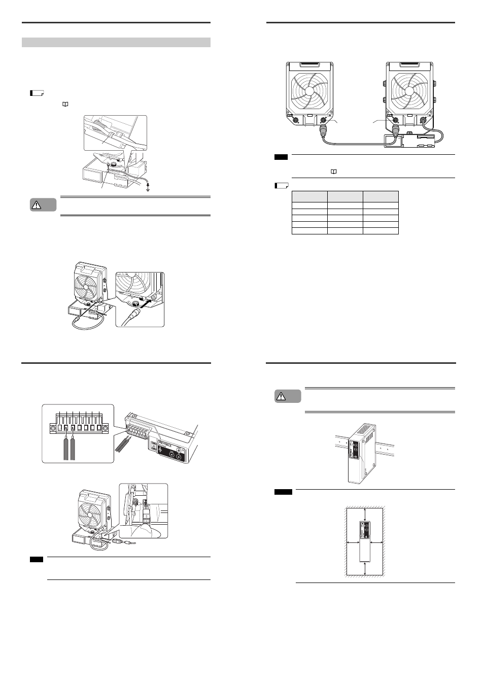
■ Installing an additional Static Elimination Blower Unit
Connect the output terminal [OUT] of the Static Elimination Blower Unit with the input terminal [IN] of a
Static Elimination Blower Unit to add using a blower-blower extension cable.
When using plural Static Elimination Blower Units in connection, connect a 24 VDC
output power supply having sufficient power capacity margin to the power output
terminals (Refer to
"Connecting the power supply" on page 5).
Current/Power consumption by the number of blower units being connected
Static Elimination Blower Unit to add
Blower-Blower extension cable
Input terminal
[IN]
Output terminal
[OUT]
Number of units
Max current
consumption
Max power
consumption
1 unit
1.2 A
29 W
2 units
2.4 A
58 W
3 units
3.6 A
87 W
4 units
4.8 A
116 W
5 units
6 A
144 W
Note:
Tip
2-2
Connection and Installation
■ Installing the Controller Unit
The Controller Unit can be mounted on the DIN rail.
Only the Controller Unit can be mounted on the DIN rail. Do not mount the
Controller Unit on the DIN rail with the Static Elimination Blower Unit fixed to
it.
Install the Controller Unit away from the wall or surrounding objects.
CAUTION
Important:
30 mm
30 mm
30 mm
30 mm