3 names and functions of parts, Static elimination blower unit, Controller unit (operation/display section) – KEYENCE SJ-F300 Series User Manual
Page 4: Names and functions of parts, Start /stop balance ion fan cond ionlevel
3
1-3
Names and Functions of Parts
Static Elimination Blower Unit
Electrode Unit
Provided with the electrode needles. Remove from the Static Elimination Blower Unit before attempting
maintenance and servicing work.
Refer to
"Performing Maintenance on the Electrode Needles" (page 9) for details about how to
remove the Electrode Unit.
Electrode needle
Generates ions from its tip.
Lock switch
Fixes the Electrode Unit to the Static Elimination Blower Unit.
Fan guard
SJ-F030: Metal
SJ-F035: Resin
■ Operation panel
START
/STOP
BALANCE
ION
FAN
COND
IONLEVEL
Lock switch
Static elimination blower
unit operation panel
Fan guard
Electrode Unit
Electrode needle
[1] Ion level alarm indicator
Lit OFF
Normal
Blinking in red
Ion level alarm has occurred.
[2] Condition alarm indicator
Lit OFF
Normal
Blinking in red
Condition alarm has occurred.
[3] Ion balance indicator
When lit, the indicator displays the ion balance.
[4] Ion level indicator
When lit, the indicator displays the ion level.
[5] Blow rate indicator
When lit, the indicator displays the blow rate setting value.
[6] Monitor
The monitor displays the ion balance, ion level, blow rate setting value in
seven indication levels.
Lights in red when the Static Elimination Blower Unit needs cleaning.
[7] START/STOP key
Used for switching start/stop.
[8] ENTER key
Used for selecting various setups.
[9] UP/DOWN key
Used for selecting and adjusting various setups.
[1]
[6]
[9]
[2]
[3] [4] [5]
[7]
[8]
1-3
Names and Functions of Parts
Controller Unit (Operation/Display Section)
[1] Power switch ..... Used for turning ON/OFF the SJ-F300 Series.
[2] Power indicator ..... Displays the power condition ON/OFF.
Lit in green
: Normal
Lit OFF
: Power OFF
Blinking in green
: Static elimination stop inputted.
Blinking in red
: Alarm has stopped.
[3] Blow rate adjusting key ..... Used for adjusting the blow rate of the Static Elimination Blower Units
being connected collectively.
[4] Ion level alarm indicator .....Blinks when the ion emission level has dropped below the setting value
due to dirt or wear of the electrode needles.
Lit OFF
: Normal
Blinking in red
: Ion level alarm has occurred.
Blinking in red
: Alarm has stopped.
*
1
Double blinking
: Under ion balancing
[5] Condition alarm indicator .... Blinks when the static elimination performance may be influenced by
instability of the installation environment (temperature, humidity,
surrounding metal objects, etc.), for example, when ions are being
absorbed by surrounding metal objects.
Lit OFF
: Normal
Blinking in red
: Condition alarm has occurred.
Blinking in red
: Alarm has stopped.
*
1
[6] Ion level alarm sensitivity setup switch ..... Used for changing the threshold value at which ion level
alarm is output.
H: High sensitivity
M: Medium sensitivity
L: Low sensitivity
[7] Condition alarm sensitivity setup switch ..... Used for changing the threshold value at which condition
alarm is output.
H: High sensitivity
M: Medium sensitivity
L: Low sensitivity
*
1
Alarm level 2, 3: [2], [4] and [5] blink simultaneously in red.
Alarm level 1:
[2] blinks in red.
[6]
[1]
[3]
[4]
[5]
[7]
[2]
1-3
Names and Functions of Parts
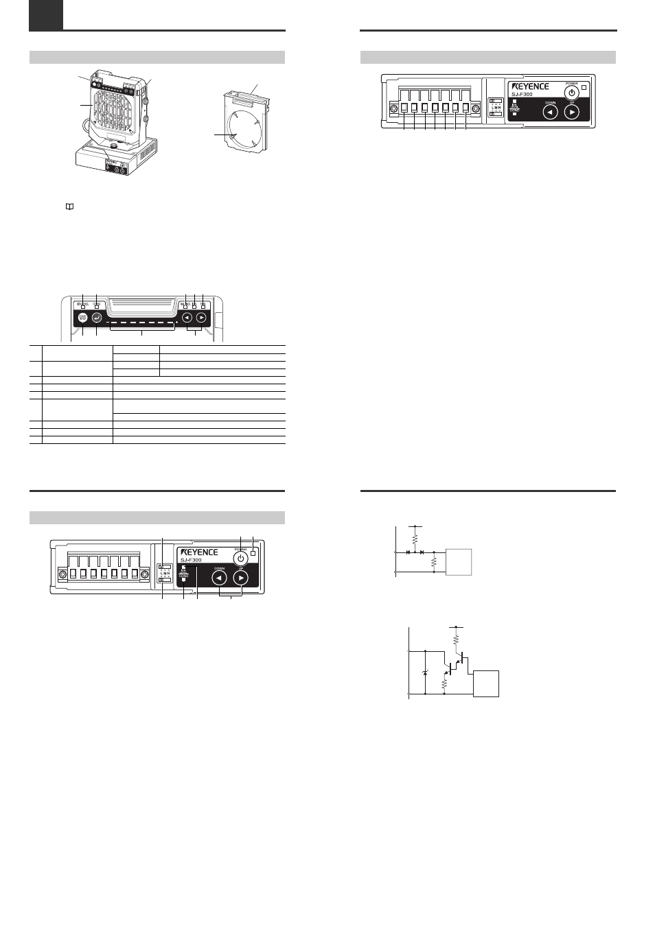
Controller Unit (I/O Terminal Section)
[1] Ground terminal ..... Be sure to connect a Class D earth.
[2] DC power terminal ..... 24 VDC ±10%
[3] 0 V terminal ..... 0 V for power and 0 V for I/O
[4] Static elimination stop input terminal ..... Static elimination can be turned ON/OFF by shorting this
terminal with [3] or [5].
[5] 0 V terminal ..... 0 V for power and 0 V for I/O
[6] Alarm output terminal ..... Outputs a signal when alarm condition has occurred.
[7] Condition/Ion level alarm output terminal .... Outputs a signal when the static elimination
performance may be influenced by instability of the
installation environment, or when the ion emission level
has dropped.
[1]
[2]
[3]
[4]
[5]
[6]
[7]
1-3
Names and Functions of Parts
■ Input circuit diagram
[4] Static elimination stop input
■ Output circuit diagram
Open collector output
[6] Alarm output, [7] Condition/Ion level alarm output
+5 V
Internal
Circuit
470
Ω
10 k
Ω
INPUT[4]
0 V[3], [5]
Input zero-voltage contact (relay, etc.) or NPN open
collector to INPUT or 0 V.
5 V
47 V
180
Ω
4.7
Ω
OUTPUT[6], [7]
40 VDC
100 mA
0 V[3], [5]
Internal
Circuit