3 performing maintenance on the air filter, Performing maintenance on the air filter, 1 timing charts – KEYENCE SJ-F300 Series User Manual
Page 11: Timing charts, 5specifications
10
4-2
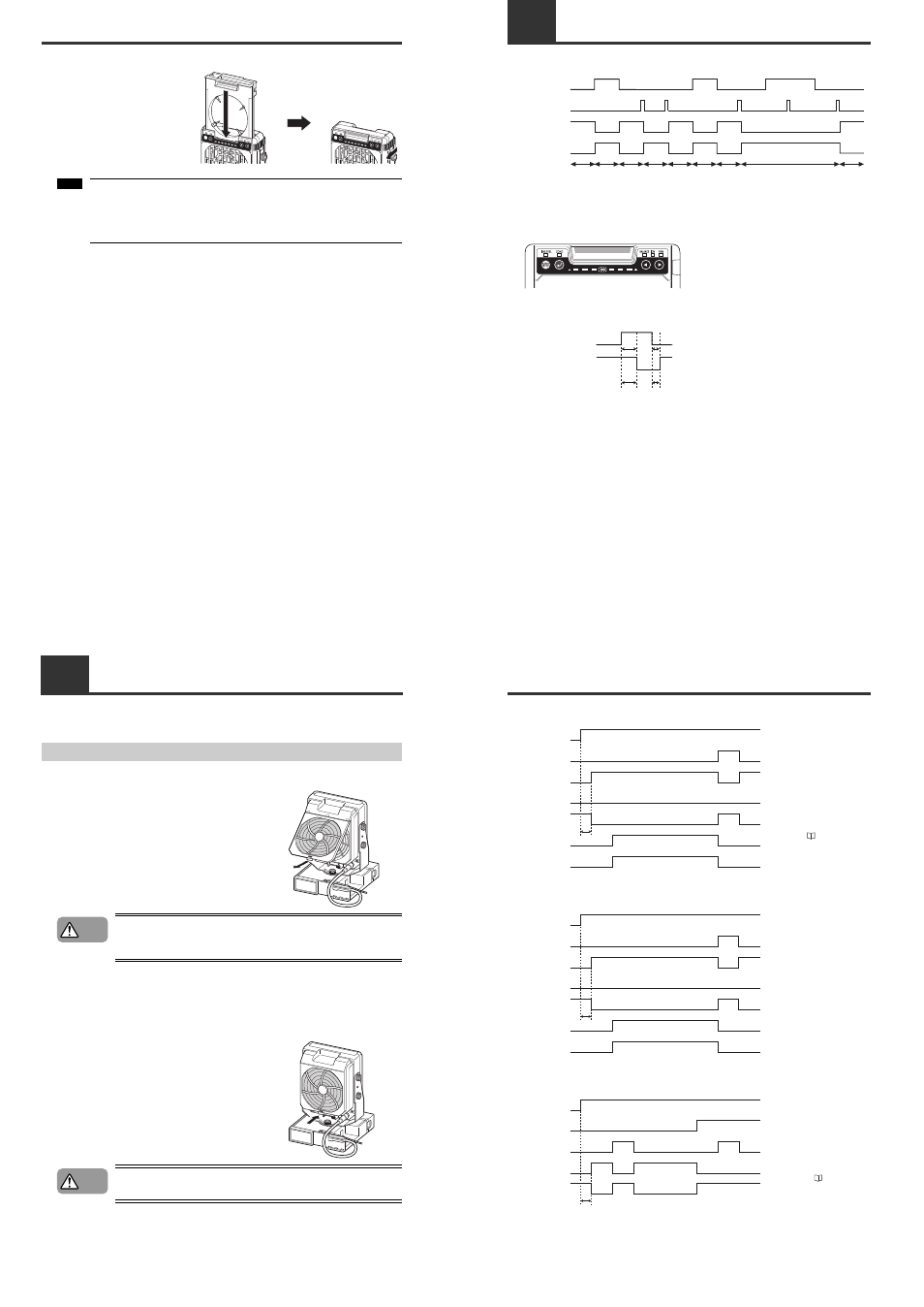
Performing Maintenance on the Electrode Needles
3
Install the Electrode Unit.
Make sure that the lock switch on the
Static Elimination Blower Unit is unlocked,
and then insert the Electrode Unit.
Make sure that the Electrode Unit is
slowly inserted all the way, and then lock
the lock switch to fasten the Electrode
Unit in place.
If cleaning the electrode needles does not improve the static elimination
performance, or the ion level alarm indicator frequently lights, a probable cause is
that the electrode needles have reached the end of their service life. Replace the
Electrode Unit.
An optional Electrode Unit for exchanging (OP-51407) is available.
START
/STOP
START
/STOP
BALANCE ION
FAN
COND
IONLEVEL
BALANCE ION
FAN
COND
IONLEVEL
Note:
4-3
Performing Maintenance on the Air Filter
When the blow rate of the static elimination blower has decreased or the air filter has got dirty, perform
maintenance on the air filter on the back panel of the Static Elimination Blower Unit.
Performing Maintenance on the Air Filter
1
Remove the air filter.
Pull the tab on the bottom of the air filter in the direction of
the arrow to remove the air filter together with the cover.
• Be sure to turn off the main power of the Static Elimination Blower Unit
before attempting maintenance. If not, there may be a risk of electric shock
or accidents.
2
Clean the air filter.
Clean the air filter of dust and dirt.
If the dirt is hard to remove, rinse the filter and dry completely
before use.
3
Attach the air filter.
Fit the air filter to the cover and attach them to the back
panel of the Static Elimination Blower Unit.
• Do not operate the blower without the air filter attached. This may cause
malfunction.
WARNING
CAUTION
5SPECIFICATIONS
5-1
Timing Charts
■ Ion generation control timing chart
* When all the connected Static Elimination Blower Units stop static elimination, alarm output turns ON.
Indicator states when static elimination is OFF
■ Input response timing chart
Normally ON Normally OFF Normally ON
Forced OFF
Normally ON Normally OFF Normally ON
Forced OFF
Normally ON
Static elimination
stop input (terminal)
ON
OFF
Static elimination
stop input (static
elimination blower)
ON
OFF
Ion emission state
Unit indicator
Emitting
No
emissions
Alarm output
ON
OFF
Normal static elimination OFF
The center LED of the monitor lights in red.
Static elimination
stop input (unit)
ON
OFF
Ion emission
state
Emitting
No
emissions
5-1
Timing Charts
■ Ion level alarm output timing chart
■ Condition alarm output timing chart
■ Alarm output timing chart
Power
ON
OFF
Static elimination
stop input
ON
OFF
Alarm indicator
Blinking
OFF
Alarm output
(N.C.)
ON
OFF
Ion emission
Emitting
No
emissions
Ion level
indicator
Max. 6.5 s
Blinking
OFF
Ion level alarm
output (N.O.)
ON
OFF
When the ion level alarm is output,
removing the cause of the alarm can
restore the normal state. One way of
restoring the normal state is to
perform maintenance on the
electrode needles.
For details on electrode needle
maintenance, see "Performing
Maintenance on the Electrode
Needles" ( page 9).
Power
ON
OFF
Static elimination
stop input
ON
OFF
Alarm indicator
Blinking
OFF
Alarm output
(N.C.)
ON
OFF
Ion emission
Emitting
No
emissions
Condition
indicator
Blinking
OFF
Condition alarm
output (N.O.)
ON
OFF
When the condition alarm is output,
removing the cause of the alarm can
restore the normal state. One way of
restoring the normal state is to
enhance the installation
environment.
Max. 6.5 s
Power
ON
OFF
Alarm indicator
ON
OFF
Static elimination
stop input
Blinking
OFF
Alarm output
(N.C.)
ON
OFF
Ion emission
Emitting
No
emissions
When the alarm is output, the
normal state can be restored by
performing one of the two available
restore methods depending on the
cause of alarm output.
For details on how to restore the
normal state, see "During an alarm
(levels 1, 2)" ( page 13).
Max. 6.5 s