3-3 wiring to the mpce monitor input terminal, English – KEYENCE SL-R11 User Manual
Page 30
Chapter 4 Wiring
4-6
4
English
ENGLISH
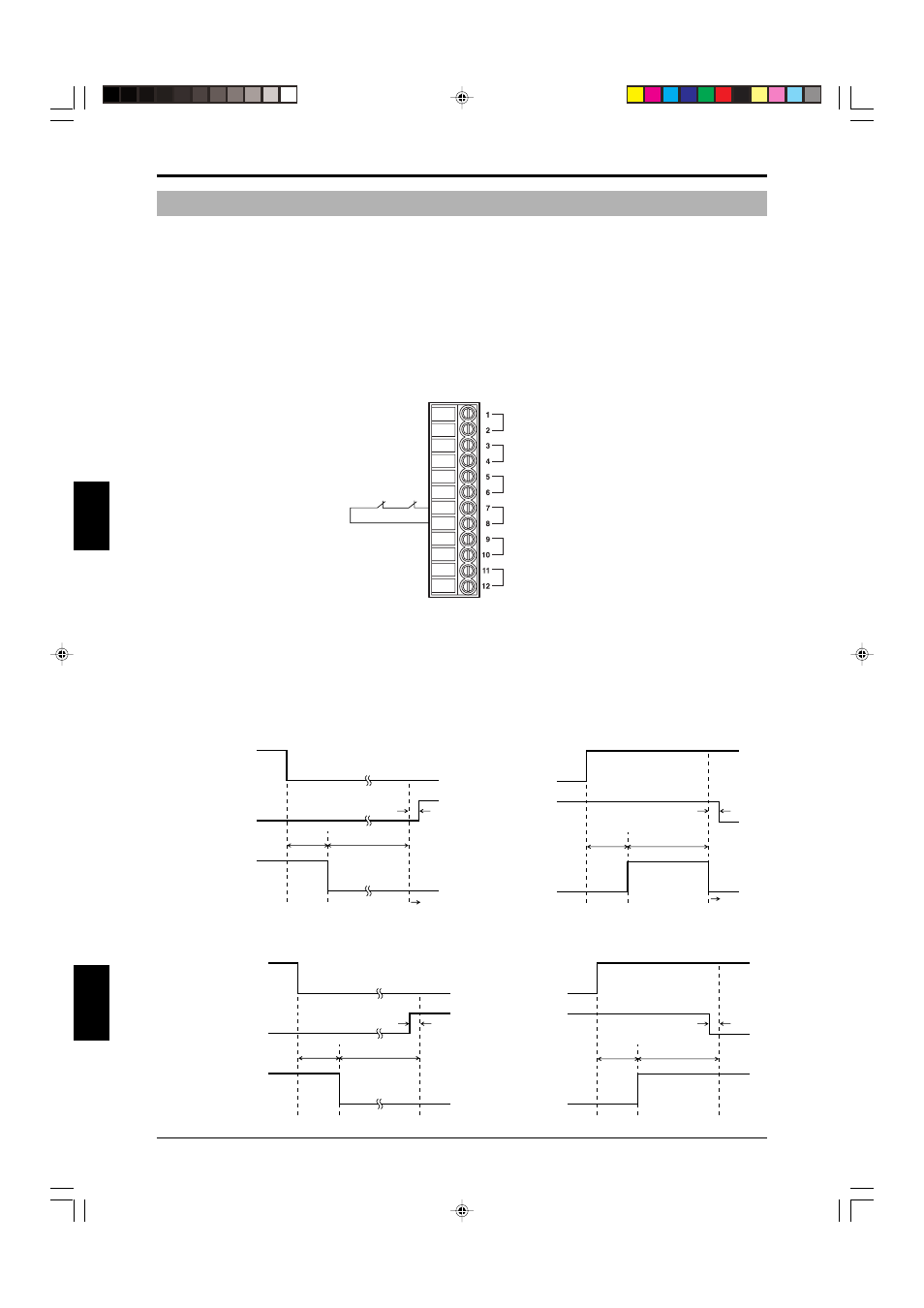
4-3-3 Wiring to the MPCE Monitor Input Terminal
Two MPCEs are used in the machine control circuit. The MPCE monitor function monitors the operation of
MPCE1 and MPCE2 to detect control circuit errors and MPCE unit errors that prevent the transmission of the
FSD output signal to the machine. When an error is detected, the SL-C Series and SL-R11 go to the lockout
condition. To enable this feature, it is necessary to set the mode switches of MPCE monitor to “Enable”
according in the instructions in section 2-11 “Mode Switch Settings” (
➮ page 2-5).
Use a device for the MPCE that has normally closed contacts and that has a maximum response delay time
of 292ms.
In addition, when connecting a MPCE to the MPCE monitor input terminal, the wiring is as shown below, so
refer to the example when wiring.
Wiring diagram
MPCE2
MPCE1
Start / Restart
input
TEST input
M/S SELECT
input
MPCE
MONITOR input
E-STOP1
input
E-STOP2
input
1.Wire the MPCE1 relay coil to FSD1.
2.Wire the MPCE2 relay coil to FSD2.
3.To enable the MPCE monitor, connect the MPCE1 normally closed contact and MPCE2 normally closed
contact in series, and then connect them to the MPCE monitor input terminal.
Timing chart
ON
OFF
ON
OFF
Clear
Blocked
FSD
24ms Max.
292ms Max.
ON
OFF
ON
OFF
Clear
Blocked
FSD
MPCE monitor
input
24ms Max.
292ms Max.
Lockout
condition
Lockout
condition
MPCE monitor
input
*
*
ON
OFF
ON
OFF
Clear
Blocked
FSD
MPCE monitor
input
24ms Max.
292ms Max.
ON
OFF
ON
OFF
Clear
Blocked
FSD
MPCE monitor
input
24ms Max.
292ms Max.
*
*
Timing chart when an error occurs
Timing chart when normal
* Depends on response time of machine’s MPCE