4 wiring, 1 method for connection to the sl-c series, 2 method for wiring to the relay output terminal – KEYENCE SL-R11 User Manual
Page 25: Warning, Chapter 4 wiring
Chapter 4 Wiring
4-1
4
ENGLISH
4 Wiring
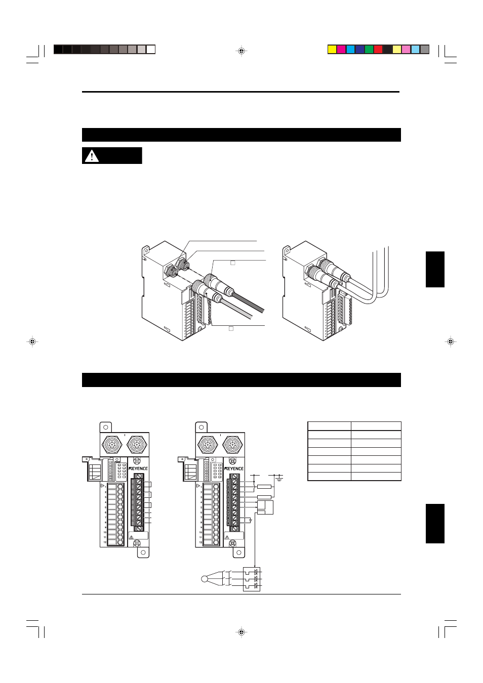
4-1 Method for Connection to the SL-C Series
WARNING
• The SL-C Series can be connected to the SL-R11 using only the following cable
combinations: SL-PC5P/SL-PC10P and SL-CC10PT/SL-CC10PR.
• The maximum length of the SL-C Series connection cables (transmitter and
receiver cables) is 30m (98.43 ft.) each.
• Using cables that exceed 30m (98.43 ft.) in length could result in unstable opera-
tion of the SL-C Series and SL-R11 and cause a serious accident leading to
serious injury or death of the machine operator.
Use the special cables to connect the SL-C and SL-R11 as shown in the figure below. Connect and secure
the cables from the SL-C to the connectors for receiver and transmitter provided on the SL-R11.
Connection 2
Connection 1
Connector for Receiver (black)
Connector for transmitter (gray)
Transmitter cable (gray)
SL-PC PT or
SL-CC10PT
Receiver cable (black)
SL-PC PR
or SL-CC10PR
* Use the following minimum bend radius when routing SL-C Series cables: 10mm (0.39") or greater for the
base of the connector that is connected to the SL-R11, and 5mm (0.2") or greater for all other positions.
4-2 Method for Wiring to the Relay Output Terminal
As shown in the table below, the SL-R11 has a relay output terminal block. This is a quick-disconnect type
terminal block.
Relay output terminal
Wiring example
Terminal No.
Name
1, 2
FSD 1
3, 4
FSD 2
5, 6
AUX
7
Not used
8
+ 24V
9
0V
FSD1
FSD2
AUX
Unused
+24V
0V
T R
POWER
FSD-ON
FSD-OFF
INTERLOCK
LOCKOUT
RESTART
TEST
MPCE
E-STOP1
E-STOP2
CAUTION
Electric shock
1
2
3
4
5
6
7
8
9
See Instruction Man
ual.
MODE SWITCH
MPCE
MONITOR
START
INTERLOCK
RESTART
INTERLOCK
1,5
2,6
3,7
4,8
MODE SWITCH
MPCE
MONITOR
START
INTERLOCK
RESTART
INTERLOCK
1,5
2,6
3,7
4,8
M
MPCE 1
MPCE 2
IN
OUT
PLC
24V
0V
MPCE 1
MPCE 2
T R
POWER
FSD-ON
FSD-OFF
INTERLOCK
LOCKOUT
RESTART
TEST
MPCE
E-STOP1
E-STOP2
CAUTION
Electric shock
See Instruction Man
ual.
MODE SWITCH
MPCE
MONITOR
START
INTERLOCK
RESTART
INTERLOCK
1,5
2,6
3,7
4,8
+24V
0V
Machine Control