5 main/sub setting, 6 test input, 7 fsd output – KEYENCE SL-R11 User Manual
Page 15: 8 aux output, English 2-5 main/sub setting
Chapter 2 Functions
2-3
2
ENGLISH
2-5 Main/Sub Setting
This is set when making a light interference prevention connection to the SL-C Series. Be sure to read about
the light interference prevention connection from the “Safety Light Curtain SL-C Series Instruction Manual.”
The light interference prevention connection function is enabled only when a maximum of 4 SL-R11s are
connected via a light interference prevention cable and the maximum number of beam axes of the SL-C
Series connected to the SL-R11 is 192, only one SL-R11 must be set to the main mode, and all of the other
SL-R11 that are connected via light interference prevention cables must be set to the sub mode.
➮ For details, See page 4-7 “4-3-4 Connecting to Main/Sub Select Input Terminal”.
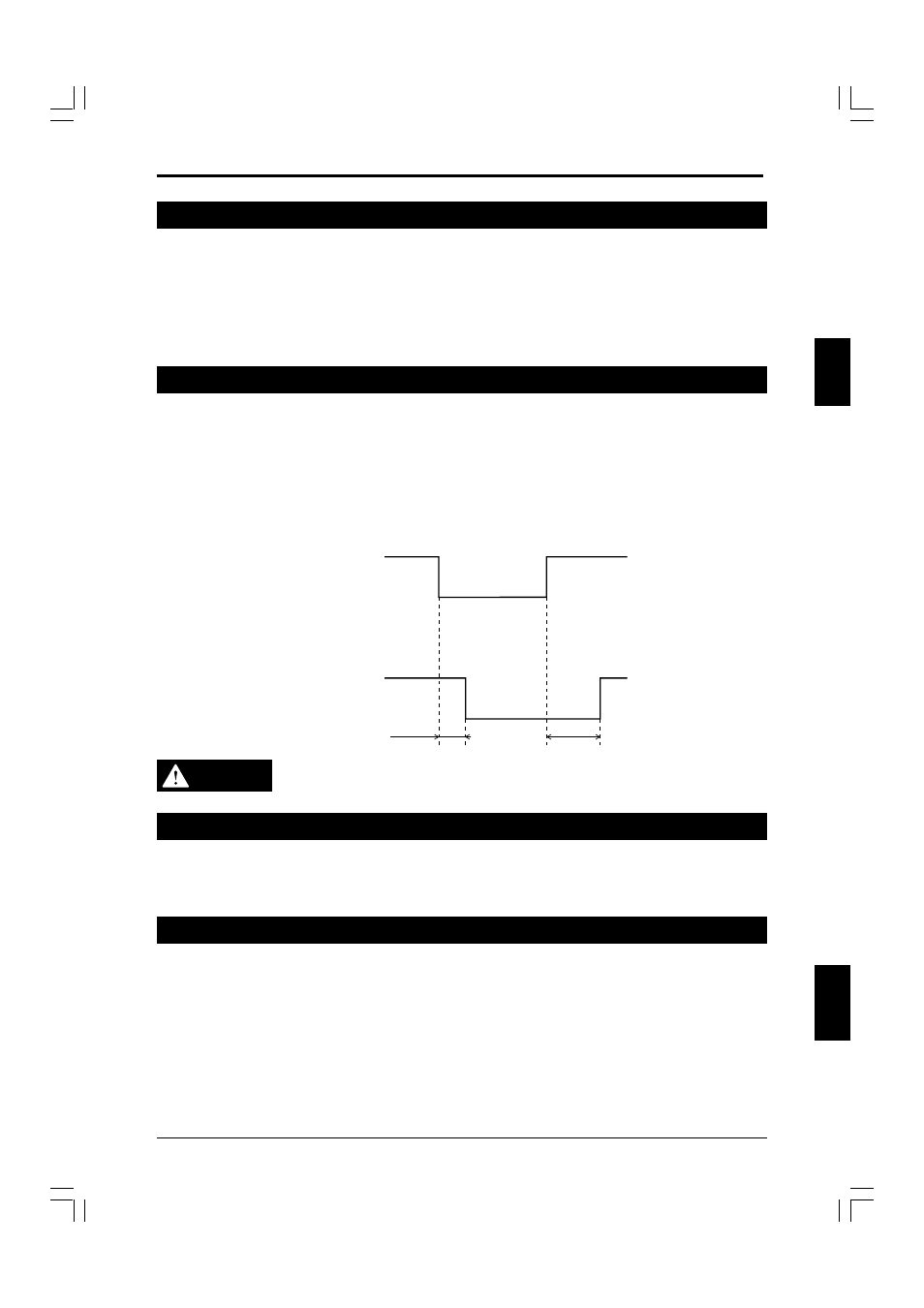
2-6 TEST Input
The test input forcefully stops light beam transmission from the transmitter by using an external input.
The test input is used to see if the machine connected to the SL-C and SL-R11 can stop within the pre-
scribed time when the FSD turns off.
For example, when the test input is performed with the SL-C in the normal state (when FSD output is on
when all beam axes are clear of any obstruction), the FSD is forced off and only one bar LED of the SL-C
flashes red. (However, this excludes when the Fixed Blanking function is used.)
This test input cannot be used when the SL-R12EX is used and the Programmable Muting Bank function is
enabled. Therefore, the Programmable Muting Bank function must be canceled to enable test input.
TEST input
ON
OFF
ON
OFF
TEST input
FSD
50ms Max.
155ms Max.
WARNING
The TEST input cannot be used as an emergency stop input. Be sure to use the E-
STOP input when using the emergency stop function.
2-7 FSD Output
The FSD output is the safety relay control output of the SL-R11. There are two FSD outputs, FSD1 and
FSD2. They both have the same operation, but if the contacts of one of the relays gets welded together, the
other relay is turned off. For this reason, FSD1 and FSD2 must be wired to form an AND circuit.
2-8 AUX Output
The AUX relay output is used to monitor the SL-R11’s FSD status using a PLC, etc. The AUX relay operates
the same as the FSD relay, but it cannot be used to build a safety system.