10 status indicators, English, Indicators – KEYENCE SL-R11 User Manual
Page 16: Status indicators, Input status indicators
Chapter 2 Functions
2-4
2
English
ENGLISH
2-9 Relay Replacement and Terminal Block Installation Removal Function
This function makes it possible to replace the relay without changing the SL-R11 wiring. This eliminates
having to redo the wiring each time the relay is replaced and limits wiring mistakes made during rewiring.
➮ For details, See page 6-1 “6-2 Relay Circuit Board Replacement”.
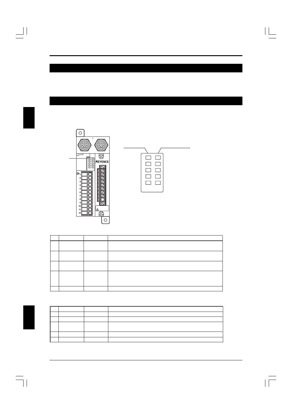
2-10 Status Indicators
Indicators that making it possible to see the (FSD) ON/OFF state or start/restart input terminal input state at
a glance are provided.
Indicators
See Instruction Man
ual.
T R
POWER
FSD-ON
FSD-OFF
INTERLOCK
LOCKOUT
RESTART
TEST
MPCE
E-STOP1
E-STOP2
CAUTION
Electric shock
See Instruction Man
ual.
Status
Indicators
POWER
FSD-ON
FSD-OFF
INTERLOCK
LOCKOUT
RESTART
TEST
MPCE
E-STOP1
E-STOP2
Input Status Indicators
Status Indicators
Status Indicators
No.
Name
Light Color
Operation Status
1
POWER
Green
Shows the power status.
Lights green when power is supplied.
2
FSD-ON
Green
Shows the FSD status.
Lights green when FSD output is on.
3
FSD-OFF
Red
Shows the FSD status.
Lights red when the FSD output is off.
4
INTERLOCK
Yellow
Lights yellow when the SL-C Series and SL-R11 are in the
start/restart interlock state, or when there is an interlock state from
the E-STOP input.
5
LOCKOUT
Red
Turns red when the SL-C and SL-R11 are in the lockout condition.
Input Status Indicators
No.
Name
Light Color
Operation Status
6
RESTART
Orange
Lights orange when the start/restart input terminal is short-circuited.
7
TEST
Orange
Lights orange when the test input terminal is open.
8
MPCE
Orange
Lights orange when the MPCE monitor function is selected and when
the MPCE input terminal is open.
9
E-STOP1
Orange
Lights orange when the E-STOP1 input terminal is short-circuited.
10
E-STOP2
Orange
Lights orange when the E-STOP2 input terminal is short-circuited.