Specifications, E gl-r-im, Response time (ossd) – KEYENCE GL-R Series User Manual
Page 9: Gl-rf, Gl-rh, Gl-rl
9
E GL-R-IM
Specifications
Specifications
*1 When the option front protection cover is installed on the one of transmitter or receiver, the Operating
distance is shorten by 0.5 m. When the front covers are installed on both of the transmitter and
receiver, the Operating distance is shorten by 1.0 m.
*2 When the GL-R is used under surrounding air temperatures between 50 to 55°C, the Maximum load
current should not exceed 350 mA.
*3 For PFHd of each GL-R, contact your nearest KEYENCE office.
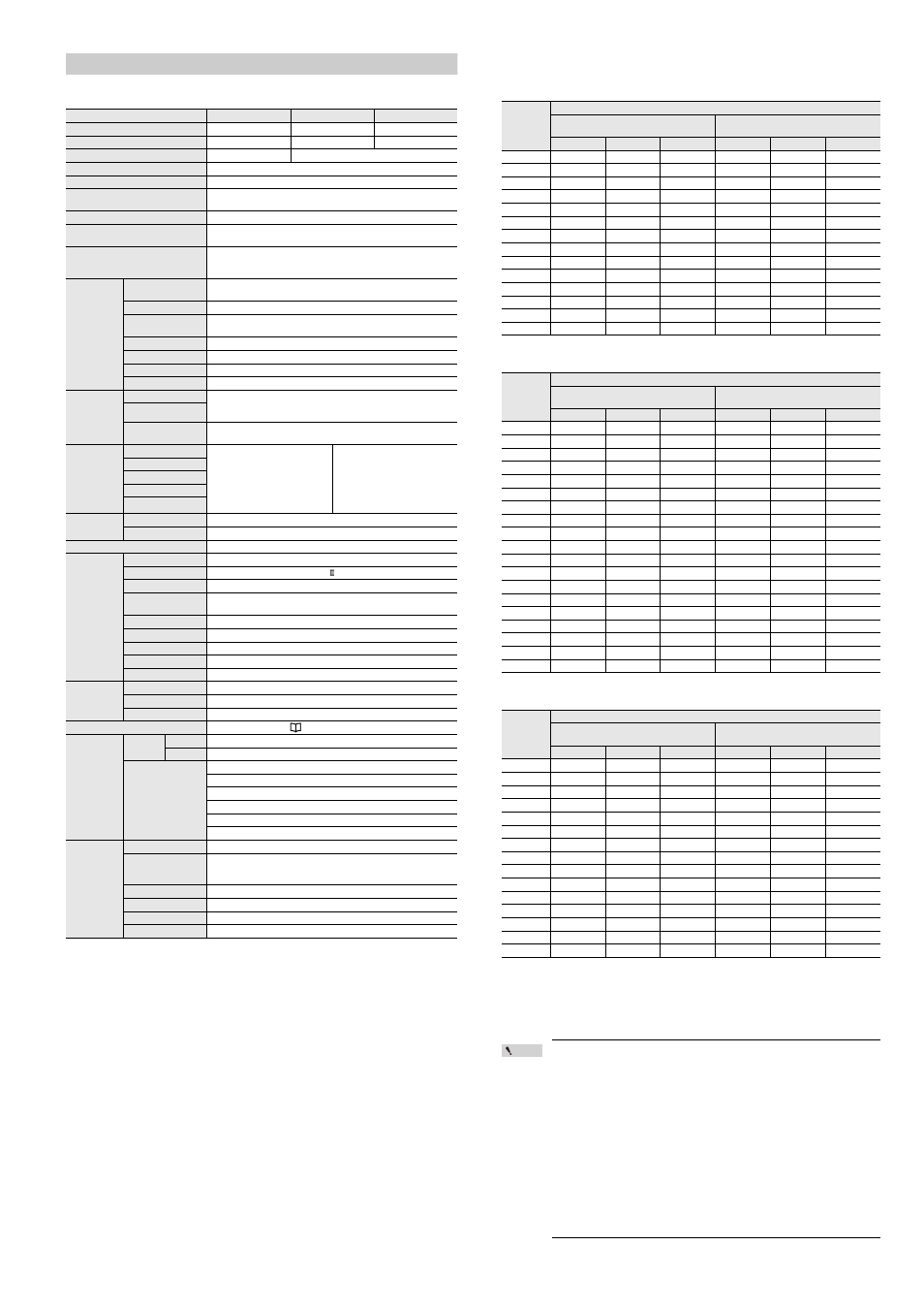
Response time (OSSD)
GL-RF
Units: ms
GL-RH
Units: ms
GL-RL
Units: ms
*1 If the interruption is present in the detection zone for less than 80 ms, the response time (OFF to
ON) will be 80 ms or more to ensure that the OSSD maintains the OFF state for more than 80 ms.
*2 "All blocked" means the situation where the GL-R operates in optical synchronization system and
the transmitter and receiver is not synchronized (top and bottom beam axes are both blocked). In
this situation, the response time is longer because the GL-R synchronizes the transmitter and
receiver first and then determines the clear or blocked.
Point
•
When the GL-R units are connected in series, the response time is calculated
according to the following steps;
1. Sum up the response time of all unit.
2. Subtract the following time from the result of previous step.
ON to OFF
One sub unit : 2 ms
Two sub unit : 4.2 ms
(When Optical synchronization system and Channel A or B)
One sub unit : 2.7 ms
Two sub unit : 5.7 ms
OFF to ON
One sub unit : 42 ms
Two sub unit : 84 ms
When connecting the GL-R32H (32 beam axes), GL-R24H (24 beam axes), and GL-
R12L (12 beam axes) in series for one-line system, the response time of each unit is
7.9 ms, 7.0 ms, and 6.6 ms respectively, and the response time (ON to OFF) is 7.9 ms +
7.0 ms + 6.6 ms - 4.2 ms = 17.3 ms.
the response time (OFF to ON) is 50.6 ms + 49.3 ms + 48.7 ms - 84 ms = 64.6 ms.
•
2.0 m/s is the maximum object detection speed of the GL-R series.
Model
GL-RF
GL-RH
GL-RL
Beam axis spacing/Lens diameter
10 mm/4
20 mm/5
40 mm/5
Detection capability
14 mm
25 mm
45 mm
Operating distance
0.2 to 10 m
*1
0.2 to 15 m
*1
Effective aperture angle
Max. ±2.5° (When operating distance is 3 m (9.84 ft.) or more)
Light source
Infrared LED (870 nm)
Response time
Optical synchronization (Channel 0) or Wire synchronization: 6.6 to 18.1 ms
Optical synchronization (Channel A or B): 6.9 to 27.4 ms
OSSD operation
Turns on when no interruptions are present in the detection zone
Synchronization between the transmitter
and receiver
Optical synchronization or Wire synchronization
(Determined by wiring)
Light interference prevention function
Prevents mutual interference in up to two GL-R systems.
Optical synchronization: prevented by Channel A and B with setting switch
Wire synchronization: prevented automatically
Control output
(OSSD)
Output
2 transistor outputs.
(PNP or NPN is determined by the cable type)
Max. load current
500 mA
*2
Residual voltage (during
ON)
Max. 2.5 V (with a cable length of 5 m (16.4 ft.))
OFF state voltage
Max. 2.0 V (with a cable length of 5 m (16.4 ft.))
Leakage current
Max. 200 A
Max. capacitive load
2.2 F
Load wiring resistance
Max. 2.5
Supplemental
output
(Non-safety-
related output)
AUX
Transistor outputs. (Compatible with both PNP and NPN)
Load current: Max. 50 mA, Residual voltage: Max. 2.5 V
(with a cable length of 5 m (16.4 ft.))
Error output
Muting lamp output
Incandescent lamp (24 VDC, 1 to 5.5 W) or
LED lamp (load current :10 to 230 mA) can be connected
Input
EDM input
< with PNP cable >
ON-voltage: 10 to 30 V
OFF-voltage: Open or 0 to 3 V
Short-circuit current:
Approx. 2.5 mA
(Approx. 10 mA for EDM)
< with NPN cable >
ON-voltage: 0 to 3 V
OFF-voltage: Open or
10 V to Power voltage
Short-circuit current:
Approx. 2.5 mA
(Approx. 10 mA for EDM)
Wait input
Reset input
Muting input 1, 2
Override input
Power supply
Power voltage
DC24 V ± 20% (Ripple P-P 10% or less, Class2)
Current consumption
Transmitter: 37 to 81 mA, Receiver: 66 to 91 mA
Protection circuit
Reverse current protection, short-circuit protection for each output, surge protection for each output
Environmental
resistance
Enclosure rating
IP65 / IP67 (IEC60529)
Overvoltage category
Ambient temperature
-10 to +55°C (No freezing)
Storage ambient
temperature
-25 to +60°C (No freezing)
Relative humidity
15% to 85%RH (No condensation)
Storage relative humidity
15% to 95%RH
Ambient light
White incandescent lamp: 3,000 lx or less, Sunlight: 20,000 lx or less
Vibration
10 to 55 Hz, 0.7 mm compound amplitude, 20 sweeps each in X, Y and Z directions
Shock
100 m/s
2
(Approx. 10 G) 16 ms pulse in X, Y and Z directions 1,000 times each axis
Material
Main unit case
Aluminum
Upper case/Lower case
Nylon (GF30%)
Front cover
Polycarbonate, SUS304
Weight
Approved
standard
EMC
EMS
IEC61496-1, EN61496-1, UL61496-1
EMI
EN55011 ClassA, FCC Part15B ClassA, ICES-003 ClassA
Safety
IEC61496-1, EN61496-1, UL61496-1 (Type 4 ESPE)
IEC61496-2, EN61496-2, UL61496-2 (Type 4 AOPD)
IEC61508, EN61508 (SIL3), IEC62061, EN62061 (SIL CL3)
EN ISO13849-1:2008 (Category 4, PL e)
UL508
UL1998
Parameter for
IEC61508
T1 (Proof test interval)
20 years
PFHd (average frequency
of a dangerous failure per
hour)
1.78×10
-9
to 5.14×10
-9
Hardware fault tolerance
1
Type of element
Type B
Failure response time
Within a response time
Safe state
OSSDs are in OFF-state
Model
Response time (OSSD)
Wire synchronization, One-line or
Optical synchronization system (Channel 0)
Optical synchronization system
(Channel A or B)
ONOFF
OFFON
*1
All blockedON
*2
ONOFF
OFFON
*1
All blockedON
*2
GL-R23F
6.9 49.2 64.4 9.3 52.7 74.0
GL-R31F
7.8 50.5 67.9 10.7 54.8 79.5
GL-R39F
8.6 51.8 71.3 12.1 56.9 85.1
GL-R47F
9.5 53.1 74.8 13.5 59.0 90.7
GL-R55F
10.4 54.3 78.3 14.9 61.1 96.3
GL-R63F
11.2 55.6 81.7 16.3 63.2 101.8
GL-R71F
12.1 56.9 85.2 17.6 65.3 107.4
GL-R79F
13.0 58.2 88.6 19.0 67.4 113.0
GL-R87F
13.8 59.5 92.1 20.4 69.4 118.5
GL-R95F
14.7 60.8 95.5 21.8 71.5 124.1
GL-R103F
15.5 62.1 99.0 23.2 73.6 129.7
GL-R111F
16.4 63.4 102.4 24.6 75.7 135.2
GL-R119F
17.3 64.7 105.9 26.0 77.8 140.8
GL-R127F
18.1 66.0 109.4 27.4 79.9 146.4
Model
Response time (OSSD)
Wire synchronization, One-line or
Optical synchronization system (Channel 0)
Optical synchronization system
(Channel A or B)
ONOFF
OFFON
*1
All blockedON
*2
ONOFF
OFFON
*1
All blockedON
*2
GL-R08H
6.6 48.7 63.1 6.9 49.1 64.2
GL-R12H
6.6 48.7 63.1 7.4 49.9 66.3
GL-R16H
6.6 48.7 63.1 8.1 50.9 69.1
GL-R20H
6.6 48.7 63.1 8.8 52.0 71.9
GL-R24H
7.0 49.3 64.9 9.5 53.0 74.7
GL-R28H
7.4 50.0 66.6 10.2 54.0 77.5
GL-R32H
7.9 50.6 68.3 10.9 55.1 80.2
GL-R36H
8.3 51.3 70.0 11.6 56.1 83.0
GL-R40H
8.7 51.9 71.8 12.3 57.2 85.8
GL-R44H
9.2 52.6 73.5 12.9 58.2 88.6
GL-R48H
9.6 53.2 75.2 13.6 59.3 91.4
GL-R52H
10.0 53.9 77.0 14.3 60.3 94.2
GL-R56H
10.5 54.5 78.7 15.0 61.4 96.9
GL-R60H
10.9 55.2 80.4 15.7 62.4 99.7
GL-R64H
11.3 55.8 82.1 16.4 63.4 102.5
GL-R72H
12.2 57.1 85.6 17.8 65.5 108.1
GL-R80H
13.1 58.4 89.1 19.2 67.6 113.7
GL-R88H
13.9 59.7 92.5 20.6 69.7 119.2
GL-R96H
14.8 61.0 96.0 22.0 71.8 124.8
Model
Response time (OSSD)
Wire synchronization, One-line or
Optical synchronization system (Channel 0)
Optical synchronization system
(Channel A or B)
ONOFF
OFFON
*1
All blockedON
*2
ONOFF
OFFON
*1
All blockedON
*2
GL-R04L
6.6 48.7 63.1 6.9 49.1 64.2
GL-R06L
6.6 48.7 63.1 6.9 49.1 64.2
GL-R08L
6.6 48.7 63.1 6.9 49.1 64.2
GL-R10L
6.6 48.7 63.1 7.0 49.3 64.9
GL-R12L
6.6 48.7 63.1 7.4 49.9 66.3
GL-R14L
6.6 48.7 63.1 7.7 50.4 67.7
GL-R16L
6.6 48.7 63.1 8.1 50.9 69.1
GL-R18L
6.6 48.7 63.1 8.4 51.4 70.5
GL-R20L
6.6 48.7 63.1 8.8 52.0 71.9
GL-R22L
6.8 49.0 64.0 9.1 52.5 73.3
GL-R24L
7.0 49.3 64.9 9.5 53.0 74.7
GL-R26L
7.2 49.6 65.7 9.8 53.5 76.1
GL-R28L
7.4 50.0 66.6 10.2 54.0 77.5
GL-R30L
7.7 50.3 67.5 10.5 54.6 78.9
GL-R32L
7.9 50.6 68.3 10.9 55.1 80.2