Checklist before operation, Inspection before operation (initial inspection) – KEYENCE GL-R Series User Manual
Page 11
11
E GL-R-IM
If the GL-R is not in an error condition
If the OSSD is not functioning normally, perform the following measures regardless of whether the
display lights indicate that the GL-R is in an error condition or not.
Checklist before operation
You are fully responsible for performing the risk assessment on your machine application, taking into
account performing maintenance and inspections, which are a critical factor for appropriate risk
assessment. In addition, it is the responsibility of the responsible personnel to train the machine
operators regarding inspection and maintenance of the machine and the GL-R.
Inspection before operation (Initial inspection)
When installation of the GL-R is completed, the responsible personnel must verify the operation of the
GL-R in accordance with the checklist shown below. Note that the following inspection items comprise
only a bare minimum inspection. KEYENCE Corporation strongly recommends including the necessary
checking items into this checklist based on the judgment of the responsible personnel since additional
criteria may be necessary depending on both the machine to which the GL-R is installed and the laws,
rules, regulations and standards in the country or region in which the GL-R is used/installed.
(1) Pre-check for installation condition
The machine under GL-R control can be caused to stop running by the OFF-state of OSSD.
The GL-R is installed so that the machine operator cannot go into or approach the hazardous area
without passing through the detection zone.
The interlock reset mechanism is installed so that it cannot be operated if there are any personnel
within the hazardous area.
The device to activate the override is installed so that it cannot be operated if there are any personnel
within the hazardous area.
The GL-R has been installed at a distance greater than or equal to the minimum safety distance
required.
If there are glossy surfaces nearby, move them so that they are beyond the minimum installation
distance according to "Installation Distance From Glossy Surfaces".
The GL-R is installed at a location free from light interference, for example fluorescent lamps.
The transmitters and receivers are paired correctly.
The beam axis spacing (detection capability) is the same between the transmitter and the receiver
when installing the GL-R.
The muting devices fulfill the conditions specified in this user's manual and the requirements of the
laws, rules, regulations and standards in the country or region in which the GL-R and those devices
are used.
The devices used to activate the override fulfill the conditions specified in this manual and
requirements of the laws, rules, regulations and standards in the country or region in which the GL-R
and those devices are used.
When the reduced resolution function is applied, the safety distance is accurately calculated based
on the detection capability, and the GL-R is installed at a distance greater than or equal to the
minimum safety distance away from the hazardous zone or hazard.
Risk assessment was performed on your own responsibility based on your machine application, and
then the installation of GL-R was also based on its result.
When the fixed blanking function is applied, a hazardous clearance that is not protected by the GL-R
may be generated between the obstacle and the GL-R. When such a hazardous clearance is
generated, an additional protective device such as a safeguard is installed.
(2) Pre-check for wiring
The GL-R power supply is 24 V DC, fulfill the conditions for the power supply as specified in this
user's manual.
The transmitter and receiver cables are installed correctly.
The two of OSSD outputs provided in the GL-R are both used as a safety-related machine control
system.
The polarity is not reversed with the connection to the power supply.
In case of using PNP output type cable, the OSSD is not short-circuited to +24V, and the load is
between the OSSD and 0V.
In case of using NPN output type cable, the OSSD is not short-circuited to 0V, and the load is
between the OSSD and +24V.
When two or more GL-R are connected in series, they are connected using the dedicated series
connection cable, which is not cut or extended.
Alert output, AUX output, Clear/Blocked output, Error output, and Interlock-reset-ready output are not
used as safety output for safety systems.
The cable sheaths are not damaged. The protection against the disconnection or short-circuit of
cable, which might be caused by crushing or being caught in a machine, is taken into account.
If two or more sets of the GL-R units are used in the vicinity of each other, the protection measures
against light interference is done through a series connection method or light interference prevention
method.
All of NON-SAFETY-RELATED functions described in this user's manual are not a part of / whole of
safety-related machine control system.
(3) Pre-check test while the machine is stopped.
You should do the following pre-check test with the test piece in order to make sure the operation of the
GL-R while the machine is stopped. In case of the detection capability of 45 mm, you should use the test
piece with a diameter of 45 mm.
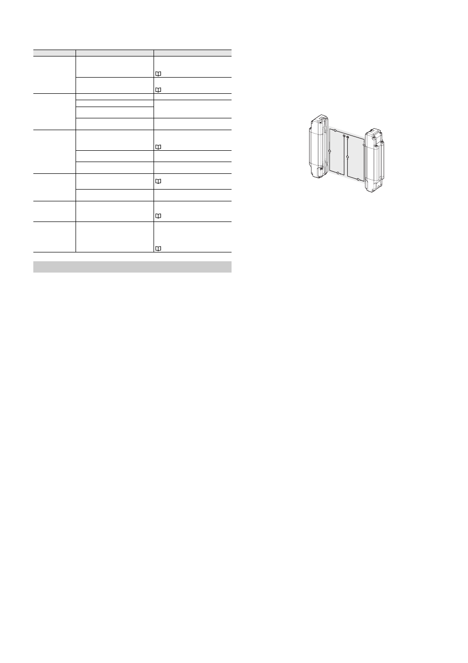
The OSSD indicator on the GL-R lights in red and the OSSD turns OFF while the test piece is present in
the detection zone. The following figure shows the movement procedure of the test piece.
The OSSD indicator and all bar LEDS light in green if no test piece is present in the detection zone.
When the EDM function is applied, the GL-R goes to an error condition and the OSSD indicator on
the GL-R lights in red if the EDM input opens while the test piece is present in the detection zone.
The bar LEDs lights in green, the OSSD indicator continues to light in red, and the interlock indicator
lights in yellow, if the test piece is removed from the detection zone. This is only applicable in case of
manual reset mode.
The OSSD indicator lights in green and the interlock indicator lights OFF if the reset input is
activated. This is only applicable in case of manual reset mode.
(4) Pre-check test while the machine is operating.
The purpose of this pre-check test is to make sure that the machine (hazards) stops its operation. This
test must be done after you completely make sure that there is nobody in the hazardous zone.
The machine stops if the test piece is present in the detection zone. It is recommended to try three
locations of test piece: near the transmitter, near the receiver, and in the central area of the detection
zone.
The machine (hazard) still stops its operation as long as the test piece is present in the specified
protection zone. This test should be done for the whole detection zone.
The machine (hazard) stops its operation when the power for the GL-R is disconnected.
Minimum safety distance is ensured, which has been calculated according to the laws, regulations,
and standards of the country and region in which the GL-R is installed.
Inspection prior to daily operation (Daily inspection)
You should check the GL-R operation and the machine operation according to the following checklist
prior to daily operation.
Note that the following inspection items comprise only a bare minimum inspection. KEYENCE
Corporation strongly recommends including the necessary checking items into this checklist based on
the judgment of the responsible personnel since additional criteria may be necessary depending on both
the machine to which the GL-R is installed and the laws, rules, regulations and standards in the country
or region in which the GL-R is used/installed.
The result of this inspection must be kept on record along with the machine log.
(1) Pre-check for installation condition
The GL-R is installed so that the machine operator cannot go into or approach the hazardous area
without passing through the detection zone.
The GL-R has been installed at a distance greater than or equal to the minimum safety distance
required.
When the reduced resolution function is applied, the safety distance is accurately calculated based
on the detection capability, and the GL-R is installed at a distance greater than or equal to the
minimum safety distance away from the hazardous zone or hazard.
When the fixed blanking function is applied, a hazardous clearance that is not protected by the GL-R
may be generated between the obstacle and the GL-R. When such a hazardous clearance is
generated, an additional protective device such as a safeguard is installed.
The GL-R is installed at a location free from light interference, for example fluorescent lamps.
The cable sheaths are not damaged. The protection against the disconnection or short-circuit of
cable, which might be caused by crushing or being caught in a machine, is taken into account.
Additionally, you should perform the following inspections as described in "Inspection before
operation".
(3) Pre-check test while the machine is stopped
(4) Pre-check test while the machine is operating
There is no change of installation that would influence the result of your original risk assessment.
Error name
Cause
Countermeasure
All Indicators are OFF.
The power is not turned ON or the power supply
voltage is insufficient.
Adjust the power supply voltage to be within the
range of specifications.
Correctly wire the power supply.
Cables are disconnected or not connected
correctly
Check the connection and reconnect the cables
if necessary.
The OSSD does not turn
ON.
(Center indicator lights in
red or does not turn ON)
Are the beam axes properly aligned?
Perform optical alignment.
Are there objects within the detection zone?
Remove all objects from the detection zone.
Ensure the transmitter to receiver distance fall
within the specified range.
Is the transmitter to receiver distance within the
specified range?
Have dust or other particles adhered to the
detection surface, thus blocking the beam axes?
Clean the surface. Gently wipe the dirt away by
using a cloth dampened with a mild detergent.
The OSSD does not turn
ON.
(Center indicator lights in
green)
If the function indicator for interlock turns ON,
the GL-R is in the interlock condition.
During manual start / manual restart mode,
OSSD only turns ON when light is received from
all of the beam axes and reset input is activated.
If the 7-segment display indicates "7", the wait
input is active.
Correctly connect the wait input.
When connected in series, are the beam axes
for the other GL-R units aligned?
Check the status of the other GL-R units
connected in series.
Beam axes are aligned,
but sometimes OSSD
turns OFF.
The receiver is affected by ambient light or light
from other photoelectric devices.
Shield the receiver from ambient light.
"Light interference prevention method"
The synchronization wire in the communication
cable is affected by external noise.
Check for noise around the cables.
The device connected to
the OSSD turns ON and
OFF very quickly
(chattering).
The self-diagnosis function periodically turns
OFF OSSD, so the device may be recognizing
this short OFF signal.
Connect a device that will not detect the regular
OSSD OFF signal.
All indicator on the
transmitter except
"POWER" turn OFF.
The GL-R operates in optical synchronization
system.
If you intend optical synchronization system, the
GL-R operates correctly and there is nothing to
do. If you do not intend optical synchronization
system, check the connection of the
synchronization 1 and 2 wire in the cable.
Start
Stop