Indicators, E gl-r-im one-line system, Wire synchronization system – KEYENCE GL-R Series User Manual
Page 7: Function indicators 7-segment display, Z upon power-up z during normal operation, Z error condition
7
E GL-R-IM
One-line system
• The series connection cable must be used to connect the transmitter and receiver.
• The unit connection cable is not needed for the transmitter.
• The wiring for the receiver is the same as optical synchronization system.
z Transmitter: Series connection cable, Receiver: 5-core cable
(1) PNP output cable
(2) NPN output cable
Wire synchronization system
z Transmitter: 7-core cable, Receiver: 7-core cable
(1) PNP output cable
(2) NPN output cable
Indicators
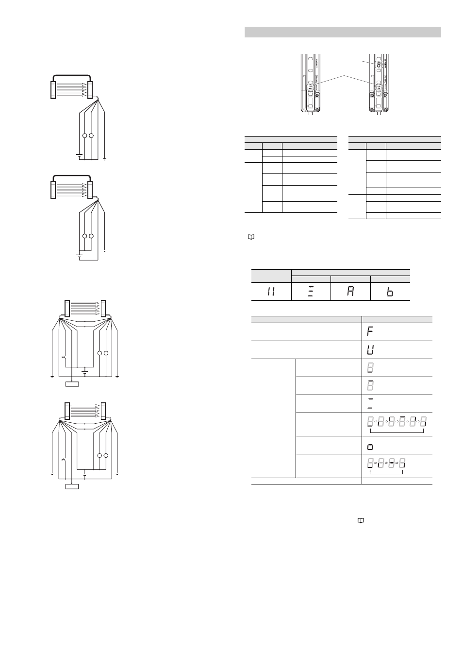
Function indicators
7-segment display
z Upon power-up
z During normal operation
*1 When not in the muted condition because conditions for initiation of muting are not met.
*2 When not in the override condition because conditions for initiation of override are not met.
z Error condition
When an error occurs, the OSSD goes to the OFF-state and the GL-R goes to the error condition.
For the 7-segment display in the error condition, refer to
R1
R2
(+
24V)
Br
own
(O
SS
D
1)
B
la
ck
(OS
SD
2)
Wh
ite
(0
V)
Bl
ue
(F
E) G
re
y
Trans
mi
tter
Re
ce
iver
R1 R2
(+
24V)
B
rown
(O
SSD
1)
Bla
ck
(OS
SD2
) W
hit
e
(0
V) B
lu
e
(F
E) G
re
y
Trans
mi
tter
Re
ce
ive
r
R1
R2
PLC
(F
E) G
re
y
(0
V)
Blu
e
(W
ai
t in
pu
t) W
hit
e
(E
rro
r o
ut
pu
t)
Bl
ac
k
(+
24
V) B
ro
w
n
Orange (Synchronization 1)
Orange/Black (Synchronization 2)
S2
(+
24
V) B
ro
w
n
(O
SSD1)
Blac
k
(O
SS
D
2)
W
hit
e
(0
V)
Blu
e
(F
E) G
re
y
Trans
mi
tter
Re
ce
iver
R1
R2
PLC
(F
E) G
re
y
(0
V)
Blu
e
(W
ai
t in
pu
t)
Wh
ite
(E
rro
r o
ut
pu
t)
Bl
ac
k
(+
24V)
Br
own
(+
24V)
Br
own
(O
SS
D
1) B
la
ck
(OS
SD
2)
Wh
ite
(0
V)
Blu
e
(F
E) G
re
y
Orange (Synchronization 1)
Orange/Black (Synchronization 2)
S2
Trans
mi
tter
Re
ce
iver
Wire synchronization
Optical synchronization
Channel 0
Channel A
Channel B
Condition
Display
Applying the reduced resolution function or fixed blanking function.
Wait input is activated.
Applying the muting
function or override
function.
Muting input 1 is activated.
Muting input 2 is activated.
Muting input 1 and 2 are both
activated
*1
.
Muted condition
Override input is activated
*2
.
Override condition.
Other than those above.
Turn OFF
Transmitter
7-segment display
Receiver
Function indicator
* When optical synchronization system is
applied, only the "POWER" indicator turns ON
on the transmitter.
Transmitter
Name
Indicator
Description
POWER
(Orange)
Light ON
Power ON (Transmitter)
Light OFF Power OFF (Transmitter)
MUTE
(Orange)
Light ON
Muted condition or
Override condition
Blinking
slowly
Muting input 1 ON
Blinking
Muting input 2 ON or
Muting input 1 ON and
Muting input 2 ON
Light OFF
Muting input 1 OFF and
Muting input 2 OFF
Receiver
Name
Indicator
Description
OSSD
(Red/
Green)
Light in
red
OSSD OFF
Light in
green
OSSD ON
Blinking in
green
Amount of received light is
unstable.
(Alert output OFF)
Light OFF Power OFF (Receiver)
INTERLOCK
(Yellow)
Light ON
Interlock condition
Blinking
Interlock reset ready condition
(Interlock reset ready output ON)
Light OFF No interlock or error condition