Wiring, E gl-r-im cable installation, Installation of the gl-r unit – KEYENCE GL-R Series User Manual
Page 5: Light interference prevention method, Cable specification
5
E GL-R-IM
Cable installation
z Cable connection to the lower part of the GL-R (The unit connection cable
and extension cable)
Reference
The unit connection cable and extension cable can be used for both the transmitter and
receiver.
z Cable connection to the upper part of the GL-R (The series connection
cable)
Reference
The series connection cable can be used on both the transmitter and receiver.
Installation of the GL-R unit
Point
Connect all cables to the GL-R before installing the mounting bracket to the GL-R unit.
The installation method differs according to the type of mounting bracket.
For details, see the manual included in the package of mounting bracket or "GL-R Series User's Manual".
Light interference prevention method
z Light interference prevention function
• When wire synchronization system is applied
The light interference prevention function automatically reduces mutual interference between GL-R
units.
• When optical synchronization system is applied
The light interference prevention function is applied according to Channel configuration.
The mutual interference is reduced between GL-R units with Channel A and Channel B.
The mutual interference is not reduced between GL-R units with Channel 0 and Channel 0, GL-R
units with Channel 0 and Channel A, or GL-R units with Channel 0 and Channel B.
Channel is configured by using the setting switch at the lower part of front side of GL-R units.
Configure the same Channel to the setting switch on both the transmitter and receiver.
For more information about the setting switch, see also
When the GL-R is in series connection, the setting switch configuration of the main unit is
applied regardless of the setting switch configuration of the sub unit.
z Series connection
Connecting GL-R in series can prevent mutual interference.
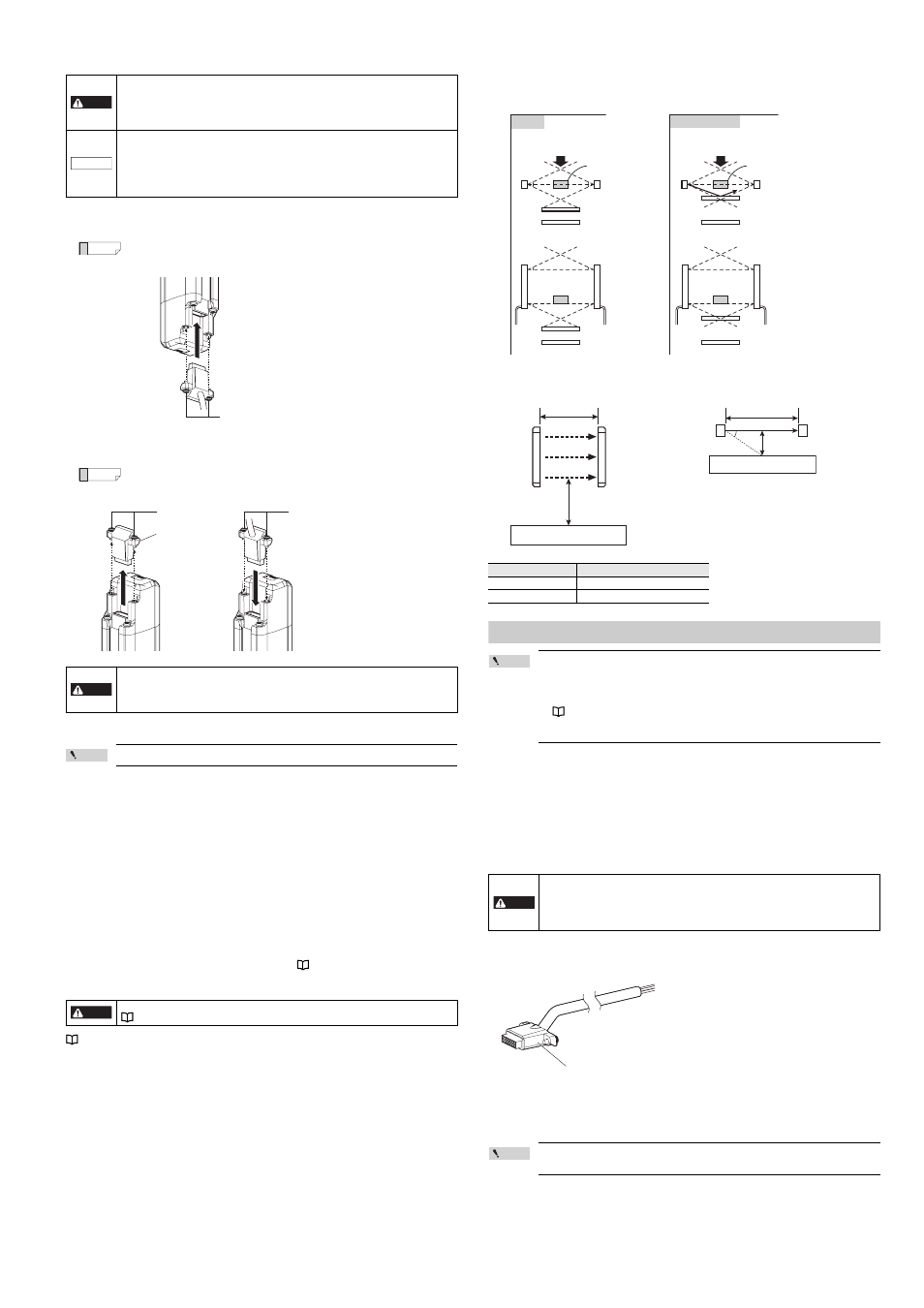
Ensuring proper GL-R installation near a glossy surface
If there is a glossy surface around the GL-R, the GL-R may be affected and may not detect an
interruption in the detection zone.
To avoid this problem, installation must be done according to the following:
When determining a specific installation distance, refer to the following values including the installation
tolerance.
Wiring
Point
• Each model is connected to one cable. Therefore, at least two cables are needed as a
system, one for the transmitter and another for the receiver.
• All cables can be used for both the transmitter and receiver.
• The combination of the wiring system and cable determines the functions that can be
used. Different types of Cables can be used for the transmitter and receiver.
• Be sure to match the numbers of conductors (core wires) when using the unit connection
cable for extension use and the extension cable.
Cable specification
(1) Cable length
1. Optical synchronization system, wire synchronization system
The sum of the length for the unit connection cable and extension cable must be 30 m or less.
This limitation applies separately to the entire transmitter cable setup and the entire receiver
cable setup.
2. One-line system
The sum of the length for all of the unit connection cables, extension cables and series cables
must be 30 m or less.
(2) Minimum cable bending radius : 5 mm
(3) Identification of connector cables
Connector colors
PNP output type cables or series connection cables : Black connectors
NPN output type cables
: Grey connectors
Point
PNP output type cables and NPN output type cables cannot be used at the same time
(mixed wiring is not possible). One type of cable must be chosen based on the application.
DANGER
• Do not remove the black gasket installed on the connector. Without this gasket the
requirement of IP65 and IP67 cannot be fulfilled.
• Securely tighten the cable connector and end cover with the screw in accordance with
the torque values specified in this user's manual. Without proper installation, the
requirement of IP65 and IP67 cannot be fulfilled.
NOTICE
• Connect the unit connection cable to the connector port on the lower part of the GL-R.
Removing the end cover on the upper part of the GL-R and connecting the unit
connection cable may result in GL-R damage.
• The end cover must be connected to the connector except when the series cable is
connected. If both the end cover and series cable are not connected to the connector, an
error occurs.
DANGER
When the GL-R units are wired by the one-line system, the end cover removed from the
upper part of the GL-R must be secured to the lower part with the screw. (Recommended
tightening torque of 0.3 N•m)
Without the end cover, the requirement of IP65 and IP67 cannot be fulfilled.
DANGER
The response time varies according to the configuration of Channel.
"Response time (OSSD)" (page 9)
M3 cross slot screws (Recommended tightening torque of 0.3 N•m)
1
M3 cross slot screws
2
M3 cross slot screws
(Recommended tightening torque of 0.3 N•m)
End cover
Operating distance "X"
Minimum installation distance "Y"
Less than 3 m
0.13 m
3 m or more
X/2 x tan5° = 0.0437 X
DANGER
• Cables must be within the lengths specified. Failure to follow this specification may
cause improper operation of safety functions, and may create a dangerous situation.
• The series connection cable cannot be cut or extended. If the cable is cut or extended,
safety features may not operate properly. Do not allow this to happen as it is extremely
dangerous.
Safe
Approaching direction
A=2.5°
Glossy surface
Area surrounding the
hazardous zone
Transmitter
Receiver
Object (Interruption)
Area surrounding the
hazardous zone
Object
(Interruption)
A
A
A
A
A
A
Glossy surface
Transmitter
Receiver
Dangerous
Approaching direction
A=2.5°
Glossy surface
Area surrounding the
hazardous zone
Transmitter
Receiver
Object (Interruption)
Area surrounding the
hazardous zone
Object
(Interruption)
A
A
A
A
A
A
Glossy surface
Transmitter
Receiver
Trans
mi
tter
Y
X
Glossy surface
Glossy surface
X
Y
Transmitter
Receiver
5°
Rec
ei
ver
Connector