Troubleshooting, E gl-r-im, If the gl-r is in an error condition – KEYENCE GL-R Series User Manual
Page 10: Current consumption, Weight
10
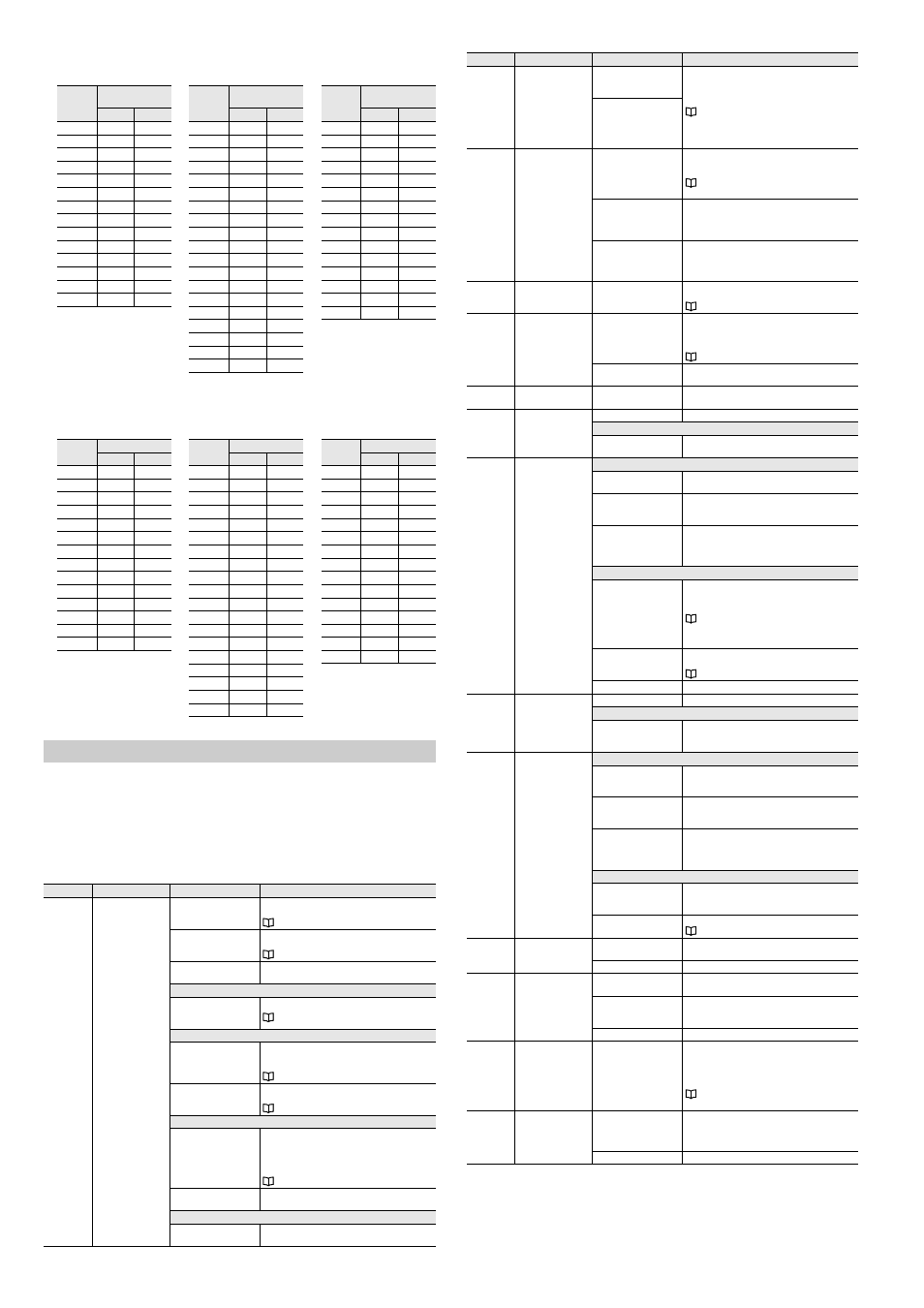
E GL-R-IM
Current consumption
*1 The above current consumption does not include the current consumed via OSSD output.
*2 If inputs other than EDM input turn on, consumption current per input increases by 2.5 mA.
Weight
Troubleshooting
If the GL-R is not functioning normally, check the GL-R indicators first.
The GL-R is in an error condition under the following situations.
•
The center indicators blink in red.
•
The 7-segment display indicates "".
If the GL-R does not demonstrate the above situations, the GL-R is not in an error condition.
If the GL-R is in an error condition
*1 All indicators on the transmitter may turn OFF.
*2 This error occurs only when the muting lamp error is configured to cause error condition by using the
configuration software.
Indication
Error name
Cause
Check and corrective action
Wiring error
The end cover on the
receiver is not connected.
Check that the end cover is installed on the receiver
correctly.
The unit connection cable
is connected to the upper
part of the GL-R.
Connect the unit connection cable to the lower part of
the GL-R.
Transmitter and receiver
are not the same model.
Check that all transmitter and receiver models are
paired correctly.
When the GL-R operates in wire synchronization system
The synchronization wire is
not wired correctly or
disconnected.
Check the wiring of the synchronization wire.
"Cable color and pin position" (page 6)
When the GL-R operates in one-line system
The unit connection cable
is connected to the
transmitter.
•
Connect the unit connection cable to the receiver.
•
Do not connect the unit connection cable to the
transmitter.
The series connection
cable is connected to the
lower part of the GL-R.
Connect the series connection cable to the upper part
of the transmitter and receiver.
When the GL-R is in series connection.
The sub unit is not
connected correctly.
•
Check for the direction of the sub unit installation.
•
Check whether the receiver of sub unit is connected
to the transmitter of main unit.
•
Check whether the total number of beam axes is
more than 240.
The sub unit is broken.
Check that the sub unit operates correctly when not in
series connection.
When the error is cleared by restarting the GL-R.
The synchronization wire is
affected by external noise.
Check for noise source (inverter, servomotor, etc.)
around the GL-R installation location and cables.
Units: mA
Units: mA
Units: mA
Model
Current
consumption (Max.)
Transmitter Receiver
GL-R23F
50
70
GL-R31F
54
71
GL-R39F
57
72
GL-R47F
60
74
GL-R55F
62
75
GL-R63F
64
77
GL-R71F
66
78
GL-R79F
67
80
GL-R87F
69
81
GL-R95F
71
83
GL-R103F
72
84
GL-R111F
74
85
GL-R119F
76
87
GL-R127F
78
89
Model
Current
consumption (Max.)
Transmitter Receiver
GL-R08H
43
66
GL-R12H
46
68
GL-R16H
50
69
GL-R20H
53
71
GL-R24H
57
72
GL-R28H
59
73
GL-R32H
61
74
GL-R36H
63
75
GL-R40H
65
76
GL-R44H
66
77
GL-R48H
68
79
GL-R52H
69
80
GL-R56H
71
81
GL-R60H
72
82
GL-R64H
73
83
GL-R72H
75
85
GL-R80H
77
87
GL-R88H
79
89
GL-R96H
81
91
Model
Current
consumption (Max.)
Transmitter Receiver
GL-R04L
37
66
GL-R06L
39
67
GL-R08L
41
68
GL-R10L
43
69
GL-R12L
46
70
GL-R14L
48
71
GL-R16L
50
72
GL-R18L
52
73
GL-R20L
54
75
GL-R22L
56
75
GL-R24L
57
76
GL-R26L
59
77
GL-R28L
60
78
GL-R30L
61
79
GL-R32L
62
80
Units: g
Units: g
Units: g
Model
Weight
Transmitter Receiver
GL-R23F
320
330
GL-R31F
430
440
GL-R39F
550
550
GL-R47F
660
670
GL-R55F
780
780
GL-R63F
890
900
GL-R71F
1000
1010
GL-R79F
1200
1200
GL-R87F
1300
1300
GL-R95F
1400
1400
GL-R103F
1500
1500
GL-R111F
1600
1600
GL-R119F
1700
1700
GL-R127F
1800
1900
Model
Weight
Transmitter Receiver
GL-R08H
210
210
GL-R12H
320
330
GL-R16H
430
440
GL-R20H
550
550
GL-R24H
660
660
GL-R28H
770
770
GL-R32H
880
890
GL-R36H
1000
1000
GL-R40H
1110
1110
GL-R44H
1220
1220
GL-R48H
1330
1340
GL-R52H
1440
1450
GL-R56H
1560
1560
GL-R60H
1670
1680
GL-R64H
1780
1790
GL-R72H
2010
2010
GL-R80H
2230
2240
GL-R88H
2450
2460
GL-R96H
2680
2690
Model
Weight
Transmitter Receiver
GL-R04L
210
210
GL-R06L
320
330
GL-R08L
430
440
GL-R10L
550
550
GL-R12L
660
660
GL-R14L
770
770
GL-R16L
880
890
GL-R18L
1000
1000
GL-R20L
1110
1110
GL-R22L
1220
1220
GL-R24L
1330
1340
GL-R26L
1440
1450
GL-R28L
1560
1560
GL-R30L
1670
1680
GL-R32L
1780
1790
Setting switch error
The configuration of the
setting switch is out of
specification.
Check the configuration of the setting switch.
The setting switch is
configured to something
other than Channel 0 in
wire synchronization
system.
Configuration error
The configuration of the
setting switch overlaps the
configuration uploaded
from the configuration
software.
Modify the configuration of the setting switch or modify
the configuration by the configuration software.
The unit configuration is
different from the
configuration uploaded
from the software.
Check the model name of main unit and sub unit and
whether the unit configuration from the software is
identical to the actual unit configuration.
The upload of configuration
has not been completed
correctly when using the
configuration software.
Upload the configuration again.
Interlock error
Interlock mode selection
input or reset input are
wired incorrectly.
Rewire the interlock mode selection input or reset input
correctly.
EDM error
EDM input is not
connected correctly.
•
If EDM function is needed, rewire the EDM correctly.
•
If EDM function is not needed, rewire the EDM and
AUX correctly or deactivate the EDM function by the
configuration software.
There is a welded contact
on the external device.
Replace the external device.
Receiver error
The receiver is affected by
ambient light.
Shield the receiver from ambient light.
Transmitter error
The transmitter is broken.
Replace the transmitter.
When the error is cleared by restarting the GL-R.
The transmitter is affected
by external noise.
Check for a noise source (inverter, servomotor, etc.)
around the GL-R installation location and cables.
OSSD1 error
OSSD2 error
When the error is cleared by restarting the GL-R.
OSSD is affected by
external noise.
Check for a noise source (inverter, servomotor, etc.)
around the GL-R installation location and cables.
There is a voltage surge
affecting the OSSD due to
an inductive load.
When the load is inductive such as relay, use a load
with a surge absorption device.
The power supply voltage
has fallen continuously or
experienced a sudden
drop.
Take measures by replacing the power supply,
increasing the power capacity, or dedicating the power
supply to the GL-R.
When the error is not cleared by restarting the GL-R.
•
OSSD is short-circuited
to 0 V or 24 V of power
supply.
•
OSSDs are short-
circuited to each other.
•
OSSD is short-circuited
to other wires.
Rewire the OSSD correctly.
Too much current is
flowing through the OSSD.
Check that the load does not consume more current
than the OSSD can handle.
OSSD is broken.
Replace the receiver.
Sub unit error
The sub unit is broken.
Replace the sub unit.
When the error is cleared by restarting the GL-R.
The sub unit or series
cable is affected by
external noise.
Check for a noise source (inverter, servomotor, etc.)
around the GL-R installation location and cables.
Communication error
*1
When the error is cleared by restarting the GL-R.
The synchronization wire is
not wired correctly or is
disconnected.
Check the connection of the synchronization wire.
The synchronization lines
in the cable are affected by
external noise.
Check for a noise source (inverter, servomotor, etc.)
around the GL-R installation location and cables.
The power supply voltage
has fallen continuously or
experienced a sudden
drop.
Take measures by replacing the power supply,
increasing the power capacity, or dedicating the power
supply to the GL-R.
When the error is not cleared by restarting the GL-R.
The synchronization wire is
not connected correctly or
is disconnected.
Check the connection of the synchronization wire.
The connection with the
GL-R in series is broken.
Replace the GL-R unit connected in series.
Muting lamp
disconnection error
*2
The muting lamp is not
connected correctly.
Check the connections.
The muting lamp is broken. Replace the muting lamp.
Muting lamp over
current error
*2
The muting lamp is not
connected correctly.
Check the connections.
Too much power is
consumed by the muting
lamp.
Make sure the muting lamp does not consume more
power than the GL-R can handle.
The muting lamp is broken. Replace the muting lamp.
Synchronization beam
axis error
When the GL-R operates in
optical synchronization
system, the fixed blanking
or muting function is
applied to both the upper
and lower beam axes (for
synchronization control).
•
Do not apply the fixed blanking or muting function to
at least the upper or lower axis.
•
Make the GL-R operate in one-line system or wire
synchronization system.
:
System error
The power supply voltage
has fallen continuously or
experienced a sudden
drop.
Take measures by replacing the power supply,
increasing the power capacity, or dedicating the power
supply to the GL-R.
The GL-R is broken.
Replace the GL-R.
Indication
Error name
Cause
Check and corrective action