Dimensions, E gl-r-im center indicator, Gl-rf – KEYENCE GL-R Series User Manual
Page 8: Gl-rh, Gl-rl
8
E GL-R-IM
Center indicator
GL-RH
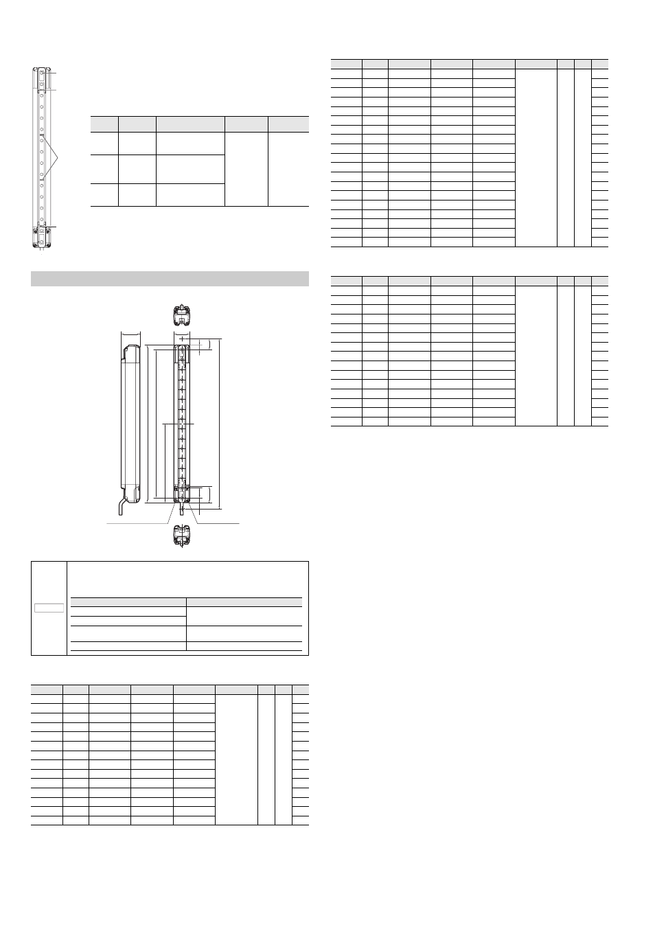
Dimensions
Units: mm
GL-RF
Units: mm
GL-RH
Units: mm
GL-RL
Units: mm
NOTICE
If the length for a single GL-R unit is 1280 mm or greater, use the following antivibration
mounting bracket additionally as an intermediate support bracket. The antivibration
mounting bracket must be selected according to the mounting bracket and installed on the
center of the GL-R unit indicated as position "G".
Model
Beam axes
A: Length
B: Detection height
C: Protection height
D: Beam axis pitch
E
F
G
GL-R23F
23
240
220
244
10
10
12
120
GL-R31F
31
320
300
324
160
GL-R39F
39
400
380
404
200
GL-R47F
47
480
460
484
240
GL-R55F
55
560
540
564
280
GL-R63F
63
640
620
644
320
GL-R71F
71
720
700
724
360
GL-R79F
79
800
780
804
400
GL-R87F
87
880
860
884
440
GL-R95F
95
960
940
964
480
GL-R103F
103
1040
1020
1044
520
GL-R111F
111
1120
1100
1124
560
GL-R119F
119
1200
1180
1204
600
GL-R127F
127
1280
1260
1284
640
Center indicator (Upper) : indicates whether interruption is present in the top
beam axis or not. (clear or blocked)
Center indicator (Middle) : indicates whether the middle axis beams are
interrupted or not.
Center indicator (Lower) : indicates whether interruption is present in the bottom
beam axis or not. (clear or blocked)
* The center indicator on the transmitter is OFF when optical synchronization
system is applied.
Center
indicator
Light OFF
red light
green light
Blinking red
light
Upper
Top beam axis
is blocked
Although the top beam axis is
unblocked, the others are
blocked
No interruption is
present in
detection zone of
the GL-R. (clear)
Error condition
Middle
Top beam axis
or Bottom
beam axis is
blocked
Although the top and bottom
beam axis are unblocked, the
middle beams are blocked
Lower
Bottom beam
axis is blocked
Although the bottom beam
axis is unblocked, the others
are blocked
Beam axis
Center
indicator
(Upper)
Center
indicator
(Middle)
Center
indicator
(Lower)
B
A
C
F
D
32
G
32.9
E
10
38
Setting switches
Interface unit connector
(only receiver)
Transmitter and Receiver
Mounting bracket
Antivibration bracket
Adjustable angle mounting bracket
Antivibration bracket for the Adjustable angle
mounting bracket
No dead zone mounting bracket
Straight mounting bracket
Antivibration bracket for the straight mounting
bracket
L-shaped mounting bracket
L-shaped mounting bracket
Model
Beam axes
A: Length
B: Detection height
C: Protection height
D: Beam axis pitch
E
F
G
GL-R08H
8
160
140
185
20
10
22.5
80
GL-R12H
12
240
220
265
120
GL-R16H
16
320
300
345
160
GL-R20H
20
400
380
425
200
GL-R24H
24
480
460
505
240
GL-R28H
28
560
540
585
280
GL-R32H
32
640
620
665
320
GL-R36H
36
720
700
745
360
GL-R40H
40
800
780
825
400
GL-R44H
44
880
860
905
440
GL-R48H
48
960
940
985
480
GL-R52H
52
1040
1020
1065
520
GL-R56H
56
1120
1100
1145
560
GL-R60H
60
1200
1180
1225
600
GL-R64H
64
1280
1260
1305
640
GL-R72H
72
1440
1420
1465
720
GL-R80H
80
1600
1580
1625
800
GL-R88H
88
1760
1740
1785
880
GL-R96H
96
1920
1900
1945
960
Model
Beam axes
A: Length
B: Detection height
C: Protection height
D: Beam axis pitch
E
F
G
GL-R04L
4
160
120
205
40
30
42.5
80
GL-R06L
6
240
200
285
120
GL-R08L
8
320
280
365
160
GL-R10L
10
400
360
445
200
GL-R12L
12
480
440
525
240
GL-R14L
14
560
520
605
280
GL-R16L
16
640
600
685
320
GL-R18L
18
720
680
765
360
GL-R20L
20
800
760
845
400
GL-R22L
22
880
840
925
440
GL-R24L
24
960
920
1005
480
GL-R26L
26
1040
1000
1085
520
GL-R28L
28
1120
1080
1165
560
GL-R30L
30
1200
1160
1245
600
GL-R32L
32
1280
1240
1325
640