Examples of wiring, E gl-r-im cable color and pin position, I/o circuit diagram – KEYENCE GL-R Series User Manual
Page 6: Symbols, Optical synchronization system, Core cable, Transmitter: 5-core cable, receiver: 5-core cable
6
E GL-R-IM
Cable color and pin position
Reference
•
When the synchronization wire 1 is wired between the transmitter and receiver, and the
synchronization wire 2 is wired in the same manner, the GL-R operates in wire synchronization
system.
•
When the synchronization wire 1 or 2 is not connected, the GL-R operates in optical
synchronization system.
•
When optical synchronization system or one-line system is applied, the input and output
functions on the transmitter are not available.
•
The functions assigned to the input and output may differ according to the configuration when
setting through the configuration software.
5-core cable
Reference
M12 connector male pin assignment
M12 connector female pin assignment
7-core cable
Reference
M12 connector male pin assignment
M12 connector female pin assignment
11-core cable
Reference
M14 connector male pin assignment
M14 connector female pin assignment
I/O circuit diagram
Reference
•
Grey wire (FE) is electrically-connected to the light curtain body case.
•
The light curtain body case and internal power signal lines are coupled by capacitor (3 kV, 100 pF).
Examples of Wiring
Symbols
R1, R2
: External device (Safety PLC, Safety relay unit, etc)
K1, K2
: External device (Force guided relay, magnet contactor, etc)
K3
: Solid state contactor
*1
S1
: Switch used for reset input
S2
: Switch used for wait input
*1
S3
: Switch used for override input
S4, S5, S6 : Switch used for muting bank inputs
L1
: Muting lamp (Incandescent lamp or LED lamp)
P1, P2
: Muting device (Self-contained photoelectric sensors, etc.)
M
: 3-phase motor
PLC
: For NON SAFETY-RELATED system control use
*1
*1 These are NON SAFETY-RELATED components.
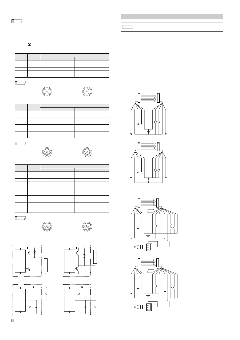
Optical synchronization system
Transmitter: 5-core cable, Receiver: 5-core cable
(1) PNP output cable
(2) NPN output cable
Transmitter: 5-core cable, Receiver: 11-core cable
When using the EDM function and interlock function
(1) PNP output cable
(2) NPN output cable
Pin No
Wire Color
Assigned function
Transmitter
Receiver
1
Brown
+24 V
+24 V
2
White
(Not in use)
OSSD2
3
Blue
0 V
0 V
4
Black
(Not in use)
OSSD1
5
Grey
FE
FE
Pin No
Wire Color
Assigned function
Transmitter
Receiver
1
White
Wait input
OSSD2
2
–
(Not in use)
(Not in use)
3
Black
Error output
OSSD1
4
Brown
+24 V
+24 V
5
Orange
Synchronization 1 (RS485_+)
Synchronization 1 (RS485_+)
6
Orange/Black
Synchronization 2 (RS485_–)
Synchronization 2 (RS485_–)
7
Blue
0 V
0 V
8
Grey
FE
FE
Pin No
Wire Color
Assigned function
Transmitter
Receiver
1
White
Wait input
OSSD2
2
–
(Not in use)
(Not in use)
3
Black
Error output
OSSD1
4
Yellow
Override input
RESET input
5
Orange
Synchronization 1 (RS485_+)
Synchronization 1 (RS485_+)
6
Orange/Black
Synchronization 2 (RS485_–)
Synchronization 2 (RS485_–)
7
Blue
0 V
0 V
8
Red
Muting lamp output
AUX (auxiliary) output
9
Red/Black
Muting input 2
EDM input
10
Brown
+24 V
+24 V
11
Pink
Muting input 1
Interlock selection input
12
Grey
FE
FE
5
4
1
2
3
5
3
2
1
4
5
8
7
3
4
2
1
6
5
8
3
7
6
1
2
4
6
10
11 12
3
4
5
2
1
9
8
7
6
10
12 11
9
8
7
1
2
3
4
5
Output circuit (PNP type cable)
Output circuit (NPN type cable)
Main
circuit
+24 V
Black or White
0 V
+24 V
Black or White
0 V
Main
circuit
Blue
Brown
Blue
Brown
E
xte
rn
al de
vic
e
E
xte
rn
al
de
vi
ce
Input circuit (PNP type cable)
+24 V
0 V
(Input line)
(Input line)
+24 V
0 V
Blue
Brown
Blue
Brown
Input circuit (NPN type cable)
Main
circuit
Main
circuit
NOTICE
The functions assigned to the input and output may differ according to the configuration
when configuring through the configuration software.
For more information, see the "GL-R Series user's Manual".
R1
R2
Trans
mi
tter
(F
E)
G
re
y
(0
V) Bl
ue
(Not
in use) W
hit
e
(Not
in use) Blac
k
(+24V
) B
ro
w
n
(+24V
) B
ro
w
n
(O
SS
D1) Blac
k
(OS
S
D2) W
hit
e
(0
V) Bl
ue
(F
E)
G
re
y
Re
ce
iver
R1
R2
(F
E
) G
re
y
(0V) Bl
ue
(Not
in use) W
hit
e
(Not
in use) Blac
k
(+
24V
) B
ro
w
n
(+
24V
) B
ro
w
n
(O
SS
D1) Blac
k
(O
S
S
D2) W
hit
e
((
0V) Blue
(F
E
) G
re
y
Trans
mi
tter
Re
ce
ive
r
PLC
M
K2
K1
OUT
IN
(+
24V)
Br
own
(OS
S
D1
) B
la
ck
(OS
S
D
2) W
hit
e
(0
V
) B
lu
e
(FE
) G
re
y
(A
UX out
put
) Red
(ED
M in
put
) Re
d/B
lack
(R
es
et
input
) Y
el
lo
w
(Inte
rloc
k mode s
elec
tio
n i
np
ut)
P
ink
(FE
) G
re
y
(0
V
) B
lu
e
(N
ot
in
us
e)
Whi
te
(N
ot
in
u
se)
Bl
ac
k
(+
24V)
Br
own
Orange (Not in use)
K1
K2
S1
K3
K1 K2
Orange/Black (Not in use)
Trans
mi
tter
Re
ce
iver
PLC
M
K2
K1
OUT
IN
(+
24
V)
Br
ow
n
(O
S
S
D
1) B
la
ck
(O
S
S
D
2)
W
hit
e
(0
V)
Blu
e
(F
E
) G
re
y
(A
UX out
put
) Re
d
(EDM
inp
ut)
Red
/Bl
ack
(R
es
et
in
pu
t) Y
ello
w
(In
te
rlo
ck
m
ode
s
ele
ct
io
n in
pu
t) Pi
nk
(F
E
) G
re
y
(0
V)
Blu
e
(N
ot i
n
us
e)
W
hi
te
(N
ot
in
us
e)
Bl
ac
k
(+
24
V)
Br
ow
n
K3
K1 K2
Orange (Not in use)
Orange/Black (Not in use)
K1
K2
S1
Tran
sm
itter
Rec
eiver