Part description, Functions and features, E gl-r-im – KEYENCE GL-R Series User Manual
Page 3: Wiring system, Setting switch
3
E GL-R-IM
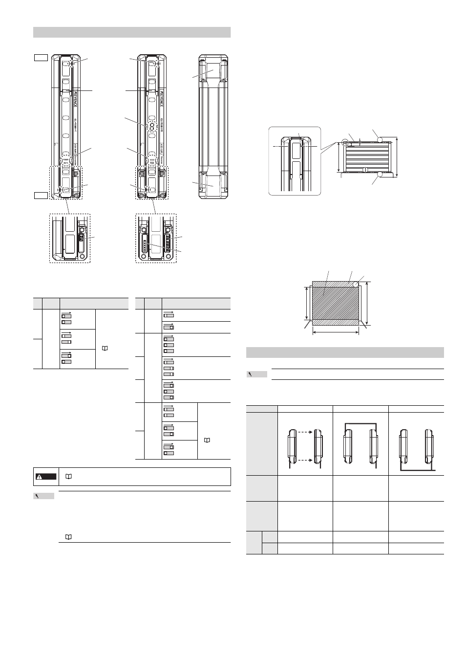
Part Description
* The side where the end cover has already been installed at shipment is the top side.
Setting switch
Point
•
The configuration of the setting switch is applied when the power is supplied.
•
When the GL-R is in series connection, the setting switch configuration of the main unit
is applied regardless of the setting switch configuration of the sub unit.
•
When the center indicator and reduced resolution are configured by using the
configuration software, the setting switch must be configured by default. Otherwise an
error occurs.
•
When the GL-R operates in wire synchronization system, the setting switch for Channel
must be configured by default. Otherwise an error occurs.
Beam center-line : An optical path joining the optical center of the emitting element on the transmitter to
the optical center of the corresponding receiving element on the receiver. The GL-R
must be installed so that the beam center-line mark on the transmitter and that on
the receiver face one another and are located at the same height.
Detection height : The height from the top beam center-line to the bottom beam center-line (length).
Protection height : An object approaching the detection zone from the top of the detection height is first
detected at point A, which is the distance of the detection capability from the top of
the detection height. The equivalent position on the bottom is called point B. The
height from the top edge of the specified target detection capability that exists at
point A to the bottom edge of the specified target detection capability that exists at
point B is called The "protection height".
The following calculation formula can be defined:
Protection height = "Detection height" + ( 2 x "the specified target detection
capability" ) – "beam axis diameter".
* Refer to the following diagram for an explanation of beam center-line, detection height and protection
height.
Detection zone
: The zone in which the specified target detection capability can be detected. The
detection zone of the GL-R indicates a square area formed with the detection height
and the operating distance. When an object of the specified target detection
capability is present in this area, the light of the GL-R is blocked, and then the
OSSD goes to OFF state.
Protection zone : The square area formed with the protection height and the operating distance,
which is broader than the detection zone. When an object of the specified target
detection capability is present in this area, the light of the GL-R is blocked, and then
the OSSD goes to OFF state.
* Refer to the following diagram for detection zone and protection zone.
Functions and Features
The functions and features of the GL-R are described in this section.
Point
For more information about these functions, see "GL-R Series User's Manual".
Wiring system
The following three types of wiring systems are available in the GL-R series.
DANGER
•
The response time varies according to the configuration of Channel.
"Response time (OSSD)" (page 9)
•
The detection capability varies according to the configuration of reduced resolution.
Transmitter
Beam center-line mark
Receiver
Back side
Center Indicators
7-segment display
Function indicators
Beam center-line mark
Setting switch
(2 switches)
Setting switch
(6 switches)
Connector for the
interface unit
(GL-R1UB)
Top
Bottom
End cover
Connector
for the unit
connection
cable
Transmitter
Receiver
Switch
No.
Function
Configuration
2
Channel
Channel 0
(Not applied)
(Default)
Use Channel for
light interference
prevention when
optical
synchronization
system is applied.
For details, refer to
the "Light
interference
prevention function"
(page 5).
Channel A
1
Channel B
2
1
2
1
2
1
Switch
No.
Function
Configuration
6
Center
indicator
ON (Green) when all beam axes
are clear (Default)
OFF when all beam axes are clear
(Green OFF)
5
Reduced
resolution
(Safety-
related
function)
Reduced resolution is not applied
(Default).
4
Reduced resolution (one optical
beam) is applied.
3
Reduced resolution (two optical
beams) is applied.
2
Channel
Channel 0
(Not applied)
(Default)
Use Channel for
light interference
prevention when
optical
synchronization
system is applied.
For details, refer to
the "Light
interference
prevention function"
(page 5).
Channel A
1
Channel B
6
6
5
4
3
5
4
3
5
4
3
2
1
2
1
2
1
Wiring system
Optical synchronization system
One-line system
Wire synchronization system
Wiring diagram
Transmitter
Receiver
Transmitter
Receiver
Transmitter
Receiver
Advantage
•
Wiring is not needed between
the transmitter and receiver.
•
The Transmitter and the
receiver can operate on
different power supplies.
•
Simplified wiring.
•
The unit connection cable is
not needed for the transmitter.
•
All functions of the GL-R are
available.
Limitation
•
The input and output functions
on the transmitter are not
available.
•
All indicators other than
"Power" are not available on
the transmitter.
•
The input and output functions
on the transmitter are not
available.
•
There is a maximum limit for
the total length of cables.
•
Wiring is needed between the
transmitter and the receiver.
Applicable
cable
Transmitter 5-core cable
Series connection cable
7-core cable
11-core cable
Receiver
5-core cable
11-core cable
5-core cable
11-core cable
7-core cable
11-core cable
Beam center-line mark
Beam center-line
Specified target detection
capability (position A)
Protection
height
Specified target detection
capability (position B)
Detection
height
a: Beam axis spacing
b: Beam axis diameter
c: Detection capability
a
b
c
Detection zone
Protection zone
Specified target detection capability
Detection height
Protection height
Operating distance