Explanation of features, Active tuning – KEYENCE AP-C30(P) Series User Manual
Page 4
4
9. Explanation of Features
■
Switching the detection range (AP-C30/C35)
The AP-C30/C35 allows you to select a detection range.
Negative pressure
Positive pressure
Compound pressure
0
to -101.3 kPa
0
to 100.0 kPa
+101.3 to -101.3 kPa
0
to -10.0 kPa
0
to 10.0 kPa
-10.0 to +10.0 kPa
Range
Display
C30
C35
Pressure type
■
Focus mode (AP-C31/C31P/C33/C33P)
Focus mode increases all display resolutions by a factor of 10.
Normal mode
Focus mode
The following focus center pressures can be selected for the models
noted in the table below.
(Unit: kPa)
AP-C31/C31P
AP-C33/C33P
-20.0 / -30.0 / -40.0 / -50.0 / -60.0 / -70.0 / -80.0
200 / 300 / 400 / 500 / 600 / 700 / 800
The current value is displayed as ±20% of the F.S. range with the fo-
cus center pressure as the reference value (0).
■
Zero shift
Zero shift input forces the pressure at that time to be defined as zero.
This feature is useful in applications that require the detection of a cer-
tain amount of pressure fluctuation without being influenced by changes
in the original pressure.
0
-0.1MPa
O.K.
Zero shift input
Zero shift input
-0.5MPa
N.G.
1MPa
(Example: leak testing)
Zero shift input received when a container is filled with air will allow the
amount of leak after a certain time to be displayed as negative pressure.
This approach eliminates the influence of small variations in the final fill
pressure of the container.
The pressure value (reference value) when zero shift input is received
can be verified from the current value display by pressing the button
to switch to the reference value display.
(
⇔
)
Press the button once more to return to the current value display.
■
Analog output
A voltage corresponding to the pressure value is output.
AP-C30/C35
AP-C30
Range
Negative pressure range
Positive pressure range
Compound pressure range
AP-C35
-101.3 to
0 kPa
0 to 100.0 kPa
-101.3 to 101.3 kPa
-10.00 to
0 kPa
0 to 10.00 kPa
-10.00 to 10.00 kPa
1 to 5V
AP-C31(P)/C33(P)
AP-C31(P)
Mode
AP-C33(P)
0 to -101.3 kPa
20.0 to -20.0 kPa
0 to 1.000 MPa
-200 to 200 kPa
1 to 5V
Standard
Focus
* The pressure value of the focus mode is based on the selected center
pressure.
■
Peak/bottom hold display
The maximum (minimum) values are displayed continuously after power to the
sensor is turned on.
The active hold display indicated below is used when the A-1 mode is selected.
How to display hold values/
From current value/reference value display
+
/ Activates peak hold display.
+
/Activates bottom hold display.
The minimum value during zero shift input is displayed for the bottom
hold during A-2 mode operation.
Resetting the peak/bottom hold values/
Pressing
for 3 seconds or more while the peak and bottom hold
values are being displayed will reset the values.
* The values will also be reset when power to the sensor is turned off,
and when the device’s detection mode or operating mode is changed.
●
During A-1 mode operation (active hold display)
The hold values are reset each time the pressure value exceeds (or falls
below) the setting, and the peak hold (bottom hold) will then vary from
this point.
Peak hold value: The peak hold value will be reset once a value is
encountered that exceeds setting P1, and new peak
values will be held from that point.
Bottom hold value: The bottom hold value will be reset once a value is
encountered that falls below setting P2, and new
bottom values will be held from that point.
■
Power-save
The value display will be turned off during power-save operation to re-
duce the amount of power consumed.
●
Use of any keys during eco mode operation will revert the sensor to
its normal display. The sensor will return to the eco display when
there is no key input for a period of 3 minutes.
■
Switching the display color
Corresponds to either output 1 or output 2 based on which setting dis-
play has been selected.
* rGr can only be set when either the F-1 or F-2 mode is selected.
Values that fall between the P1 and P2 settings will be displayed in
green, while values outside that range will be displayed in red.
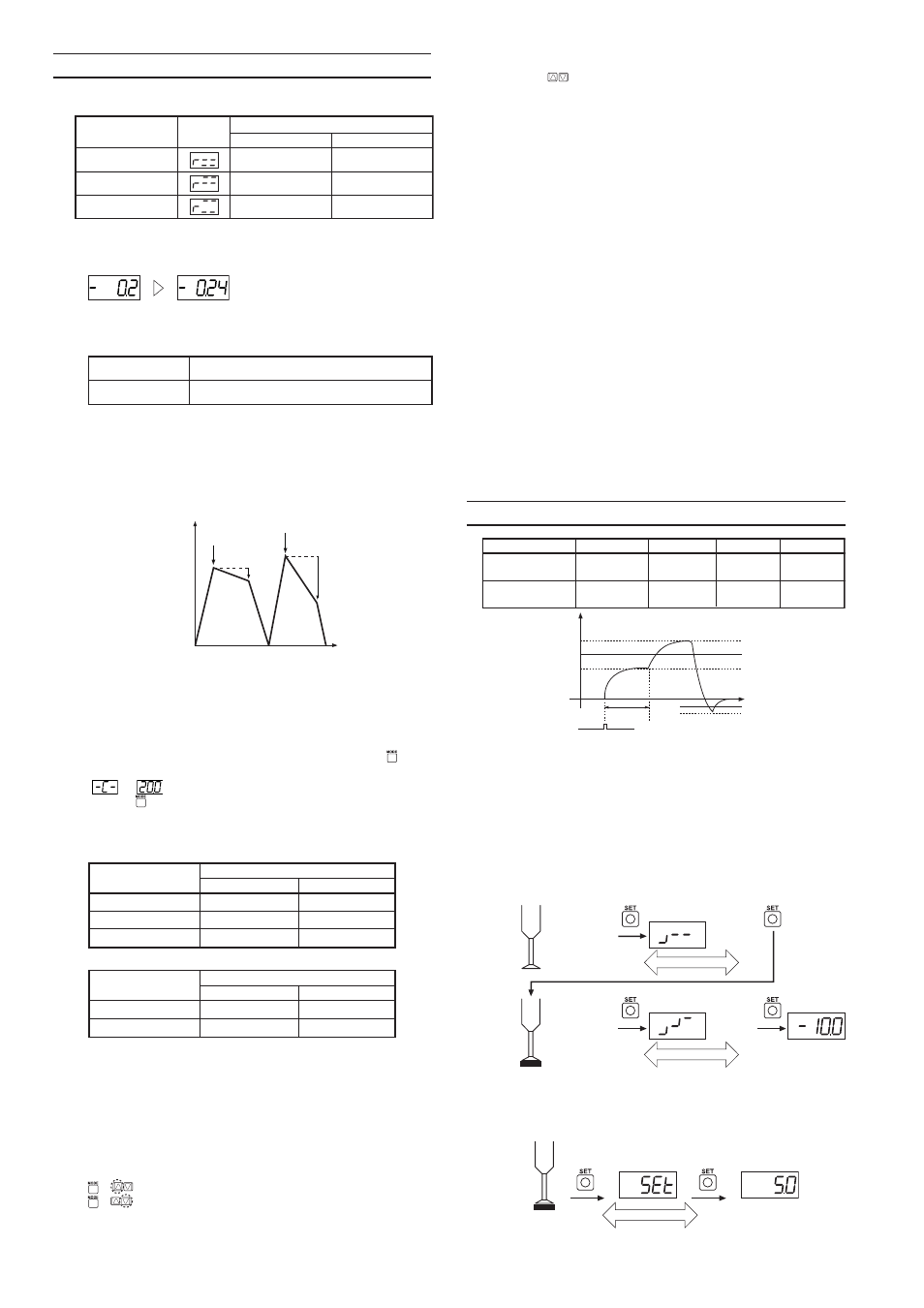
10. Active Tuning
Active 2 point tuning
Active 1 point tuning
Suction
Vacuum burst
P1
P2
T1
Automatic
configuration
_
_
Automatic
configuration
Manual
configuration
_
Application
Type
P2
P1
Time
Zero shift input
T1
V
acuum
■
Perform these steps first
• Select the setting display as indicated below before performing the
tuning procedures.
Active 2 point tuning: Select either P1 or T1 for the setting display.
Active 1 point tuning: Select P2 from the settings display.
• Connect the external signal to the zero shift input.
■
Active 2 point tuning / a tuning method suited for auto-
matically configuring suction pick-up detection pressures
The zero shift timer setting is manually configured, and the sensor auto-
matically selects the best pressure setting (P1) for this value.
Step 1)
Step 2)
Device operation
with no target
object present
Operation
for several
cycles
Operation
for several
cycles
Device operation
with target
object present
Sensitivity
difference
display
Sampling
Sampling
Start
Start
Finish
Finish
■
Active 1 point tuning / tuning optimized for vacuum burst
detection
The sensor automatically selects the best pressure setting (P2) for
vacuum burst detection.
Target object
present
Setting
display
Sampling
Start
Finish
* Cannot be used to detect vacuum burst pressure when operating in
focus mode (AP-C31/C31P).