Connection method and diagrams, Precautions for safe use, Detection mode operation – KEYENCE AP-C30(P) Series User Manual
Page 2: Ap-ao1 panel mounting bracket, Caution, Analog output circuit
2
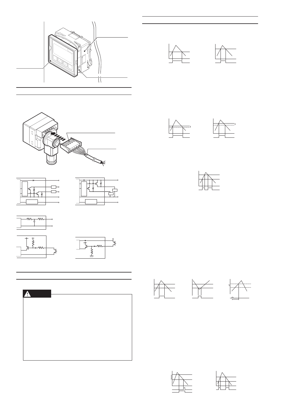
AP-AO1 Panel mounting bracket
SET
AP-C33
MODE
MP
a
SET
AP-C40
MODE
MP
a
Panel mounting ring
Panel-mounted sample
Front protective
cover
Panel-mounted sample
5. Connection Method and Diagrams
Insert the included connector-tipped cable into the sensor’s connector.
Position the connector so that the side of the connector where the metal-
lic contacts are visible is facing up.
Connector cable
Side where the metallic
contacts are visible faces up.
Input/output circuit
(AP-C30/C31/C33/C35)
(AP-C31P/C33P)
12 to 24 VDC
5 to 40 VDC
5 to 40 VDC
0V
Main cir
cuit
Ov
er
curr
ent
pr
ot
ection cir
cuit
Load
Load
Input/output
circuit
Analog output/
zero shift input: switchable
Brown
Blue
Black
White
Pink
12 to 24 VDC
0V
Main cir
cuit
Ov
er
curr
ent
pr
ot
ection cir
cuit
Input/output
circuit
Analog output/
zero shift input: switchable
Brown
Blue
Black
White
Pink
Load
Load
Analog output circuit
Analog
output (1 to 5 V)
0 V
Main
cir
cuit
Blue
Pink
Zero shift input circuit (NPN)
Zero shift input circuit (PNP)
(Short-circuit current 5 mA max.)
Main
cir
cuit
Blue
Pink
12 to 24 VDC
Main
cir
cuit
Pink
(Short-circuit current 5 mA max.)
Brown
Use non-contact input device such as open-collector.
6. Precautions for Safe Use
Follow these guidelines. Failure to do so may result in product damage.
CAUTION
■
Connections
Input/output circuit
●
Always ground the frame ground terminal when using an off-the-
shelf switching regulator.
●
Use separate conduits for power line and high voltage lines, since
use of a common conduit may result in device malfunction.
●
Improper wiring may result in the device becoming excessively hot
or in device damage.
■
Other
●
Do not use this sensor with corrosive gasses or liquids.
●
Do not insert objects such as wire into the pressure insertion area.
Doing so may result in the device failing to operate properly due to
damage to the pressure-sensitive elements.
●
Do not use sharp-tipped objects to press the setting keys.
7. Detection Mode Operation
■
General-purpose mode (F-1)
This mode allows the user to configure 2 detection points.
Control output 1: Turns ON when pressure exceeds setting P1.
Control output 2: Turns ON when pressure exceeds setting P2.
P1
0
Output 1 OFF
ON
OFF
P2
0
OFF
ON
OFF
Output 2
* Hysteresis is a standard 0.5% of F.S. when operating in general-purpose
mode and application modes 1 and 2. During focus mode operation, it is
0.2% of F.S.
■
Variable hysteresis mode (F-2)
Two detection points may be user-configured, and hysteresis for both
may also be set.
Control output 1: Turns ON when pressure exceeds setting P1. Turns OFF
when pressure drops the selected hysteresis amount
below P1.
Control output 2: Turns ON when pressure exceeds setting P2. Turns OFF
when pressure drops the selected hysteresis amount
below P2.
P1
H1
Output 1
OFF
ON
OFF
0
P2
OFF
ON
OFF
H2
0
Output 2
■
Window mode (F-3)
The user may select a pair of upper (Hi) and lower (Lo) thresholds,
and the sensor turns OFF when the pressure falls outside of the result-
ing range.
* Control output 1 is a standard 0.5% of F.S. During focus mode opera-
tion, it has a hysteresis of 0.2% of F.S., and control output 2 has a
hysteresis of 0.
Hi
Lo
Output1/Output2 OFF ON
ON
OFF
OFF
0
■
Application mode 1 (A-1)
This detection mode is optimum for use in suction detection applica-
tions.
Recommended sensor heads: AP-C30/C31/C31P
Control output 1: Suction pressure detection.
Turns ON when pressure exceeds setting P1.
Control output 2: Detection and confirmation of vacuum burst pressure
detection (or vacuum ultimate pressure).
Turns ON when the pressure falls below setting P2.
* Cannot be used to detect vacuum burst pressure with
the AP-C31/C31P when operating in focus mode.
Standard mode operation only.
Zero shift:
The zero point is shifted immediately after the zero
shift timer is set following the activation of zero shift
input.
P1: Pressure setting for control output 1.
T1: Zero shift timer setting (ms) < Variable between 0 and 1,999 ms
P2: Pressure setting for control output 2.
* P2 is unrelated to zero shift and is always based on the current ambi-
ent pressure.
■
Application mode 2 (A-2)
This mode is optimum for use in leak test applications.
Recommended sensor head: AP-C33/C33P
Control output 1: Leak pressure detection.
Turns ON when pressure falls below setting P1.
*Output only when receiving zero shift input.
Control output 2: Window comparator output for detection of fill pressure.
Turns OFF when pressure falls outside the range deter-
mined by upper (Hi) and lower (Lo) thresholds.
* Fill pressure values are displayed with the center pres-
sure as 0 during focus mode operation.
P1: Pressure setting for control output 1.
Hi: Upper threshold setting for control output 2.
Lo: Lower threshold setting for control output 2.
* The Hi and Lo values are unrelated to zero shift and are always based
on the current ambient pressure.
P1
Output 1 OFF
ON
OFF
0
0
Output 2 OFF
ON
OFF
P2
0
0
Shift
Zero shift input
T1
P1
Output1
Zero shift input
OFF
ON
OFF
ON
0
Hi
Lo
Output 2 OFF
ON
OFF
OFF
ON