KEYENCE AP-C30(P) Series User Manual
Ap-c30 (p) series instruction manual, Ultra-compact digital pressure sensor, Safety precautions
1
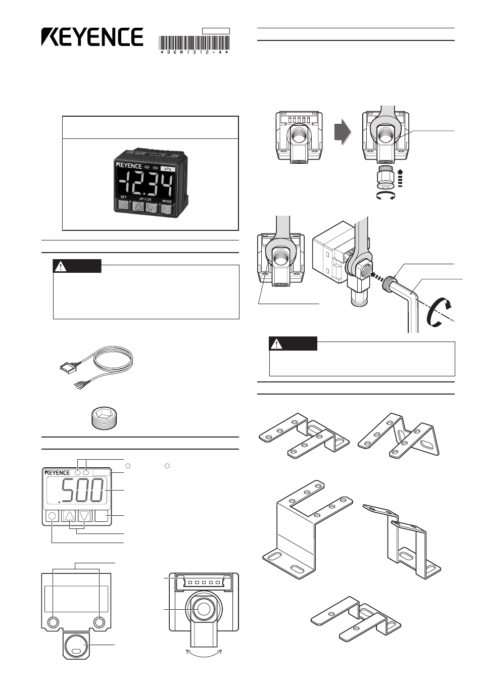
Ultra-compact Digital
Pressure Sensor
AP-C30 (P) Series
Instruction Manual
1. Safety Precautions
WARNING
●
Do not use this product in safety circuits such as those designed to
protect human workers.
●
This product does not employ an explosion-proof construction. Do
not use it in the presence of flammable gasses, liquids, or powders.
●
This is a direct current power supply type sensor. Application of an
alternating current may result in explosion or fire.
■
Accessories
3. Pipe Connections
You can select from one of two pressure ports: one on the back of the
sensor that can accommodate a pipe leading directly away from the back
of the sensor, and one on the side of the sensor to accommodate a pipe
leading away from the sensor at a right angle.
1) The pressure port is 1/8 of Rc (PT). Commercially available air pres-
sure joints and nipples can be used with the port.
When attaching the joint, use a wrench to hold the pressure port in
place as illustrated below.
Hold in place
with wrench
(12mm).
2) Attach the included valve plug to the pressure port not being used.
Hold in place with
wrench (12 mm).
Hexagonal
wrench (5mm)
Valve plug with
hexagonal hole
CAUTION
• Do not use a torque in excess of 10 Nm when tightening the joint.
Doing so may damage the joint.
• Apply sealing tape when attaching the joint in order to prevent air leaks.
4. Mounting Brackets (option)
Dedicated mounting hardware is available for the sensor, allowing it to
be installed in a range of locations.
Horizontal mounting bracket
Wall mounting bracket
(AP-BO1)
(AP-BO2)
Faceplate/ceiling mounting bracket
Tilted mounting bracket
(AP-BO3)
(AP-BO4)
Substitution bracket
(AP-BO5)
●
1 connector cable (2 m)
●
1 unit scale label
(AP-C33 only)
2. Part Names
SET
AP-C33
MODE
MPa
2
1
Pressure display unit
Pressure display
Mode button
Manual adjustment button
Set button
Wiring
connector
Pressure
port (rear)
Pressure port
(side)
Mounting screws
(M3 x 2)
Operational indicator
Output 1
Output 2
1
2
Approx. 90
●
1 valve plug with hexagonal hole
●
1 instruction
manual
96M1312
1.
Safety Precautions
2.
Part Names
3.
Pipe Connections
4.
Mounting Brackets (option)
5.
Connection Method and Diagrams
6.
Precautions for Safe Use
7.
Detection Mode Operation
8.
Sensor Configuration
9.
Explanation of Features
10.
Active Tuning
11.
Default Mode Settings (Initialization)
12.
Specifications
13.
Ambient Pressure Compensation
14.
Key Lock
15.
Error Displays and Corrective Actions
Document Outline
- 1. Safety Precautions
- 2. Part Names
- 3. Pipe Connections
- 4. Mounting Brackets (option)
- 5. Connection Method and Diagrams
- 6. Precautions for Safe Use
- 7. Detection Mode Operation
- 8. Sensor Configuration
- 9. Explanation of Features
- 10. Active Tuning
- 11. Default Mode Settings (Initialization)
- 12. Specifications
- 13. Ambient Pressure Compensation
- 14. Key Lock
- 15. Error Displays and Corrective Actions
- WARRANTIES AND DISCLAIMERS