Part names, 12 3 high auto gain low 0 mon(v) mon(ma), Controller part names – KEYENCE LK-2000 Series User Manual
Page 7: Sensor head
7
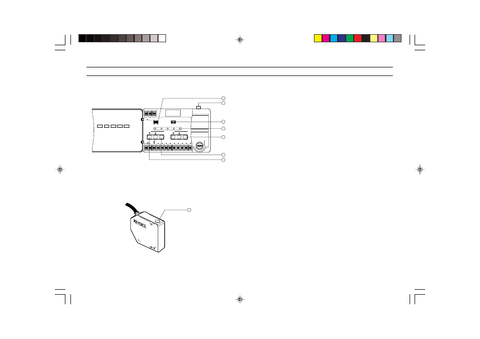
Controller
PART NAMES
1
1
1
1
1 DIP switches
Set alarm hold function, key-lock function, and averaging function.
2
2
2
2
2 Sensor head connector
3
3
3
3
3 Sensitivity setting switch
Changes the received light sensitivity according to the reflectance of
the target. (
➮ Refer to p. 15)
4
4
4
4
4 Indicators
TIMING: Lights during synchronous (timing) input.
STABILITY: Lights yellow or green when a target is within the
measuring range. Lights red when a target is out of the measuring
range, or when the light quantity is insufficient or excessive.
BRIGHT: Lights when the light quantity is excessive.
DARK: Lights when the light quantity is insufficient.
LASER ON: Lights during laser emission.
5
5
5
5
5 SPAN adjustment keys
Finely adjusts the inclination of the analog output.
6
6
6
6
6 AUTO ZERO/RESET keys
Resets the analog output to 0 V (12 mA) at any point. Cancels
AUTO ZERO function.
7
7
7
7
7 SHIFT adjustment key
Finely adjusts the 0-point position of the analog output.
8
8
8
8
8 Operation indicator
Lights yellow or green when a target is within the measuring range.
Flashes yellow when a target is out of the measuring range, or when
the light quantity is insufficient or excessive.
Sensor head
ON
OFF
REMOTE
24 VDC IN
GND
TIMING
ZERO
GND
ALARM
GND
NEAR
FAR
+
-
SPAN
SHIFT
ZERO/RESET
ZERO/RESET
TIMING
STABILITY
BRIGHT
DARK
LASER ON
1
2
3
HIGH AUTO
GAIN
LOW
0
MON(V)
MON(mA)
LASER
2
1
3
4
5
6
7
LK-031
LASER ON
8