Power-on, 12 3 high auto gain low 0 mon(v) mon(ma), Installation – KEYENCE LK-2000 Series User Manual
Page 10: Sensor head
10
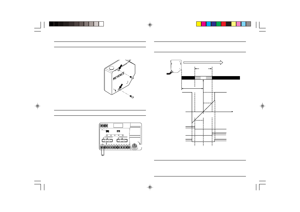
INSTALLATION
Adjust the distance between the sensor head and target by checking the
sensor head’s LED operation indicator.
OUTPUT CHARACTERISTICS AND LED INDICATOR
[LK-031/036/081/086/501/503 IN LONG RANGE MODE]
Note 1: The NEAR or FAR output turns on only when the target moves slowly from
the inside to the outside of the measuring range.
Note 2: When measurement is affected by the scattered reflection of a mirror-
surfaced target, the operation indicator remains in the normal status, and the alarm
output is not turned on even if the target is out of the measuring range.
LK-031
Sensor head
Secure the LK-031/036 and LK-
081/086 with M4 screws, or the LK-
501/503 with M5 screws using the
two mounting holes indicated by the
arrows.
OFF
ON
REMOTE
24 VDC IN
GND
TIMING
ZERO
GND
ALARM
GND
NEAR
FAR
+
-
SPAN
SHIFT
ZERO/RESET
ZERO/RESET
TIMING
STABILITY
BRIGHT
DARK
LASER ON
1
2
3
HIGH AUTO
GAIN
LOW
0
MON(V)
MON(mA)
24 V
LK-031
Measuring
range
Out of
measuring
range
Out of
measuring
range
30 mm
(80 mm)*
(500 mm)**
Analog
output
25
(65)*
(250)**
ø250 µm
(ø350 µm)*
(ø1200 µm)**
ø30 µm
(ø70 µm)*
(ø300 µm)**
ø250 µm
(ø350 µm)*
(ø1200 µm)**
35
(95)*
(750)**
30
(80)*
(500)**
–5 V
(4 mA)
5 V
(20 mA)
12 V
(31.2 mA)
Spot diameter
LED operation indicator
Flashing yellow
Flashing yellow
Yellow
Yellow
Green
Measuring distance (mm)
OPEN
CLOSED
OPEN
CLOSED
OPEN
CLOSED
NEAR output
(N.C.)
FAR output
(N.C.)
Alarm output
(N.C.)
Data in ( )* applies to the LK-081/086.
Data in ( )** applies to the LK-501/503 in long-range mode.
POWER-ON
1. Provide a 24 VDC power
supply to terminals No. 1
and 2.
2. Set the key-operated switch
to the ON position. The
laser beam is emitted from
the sensor head and the
unit is ready to perform
measurement. (Connect the
REMOTE and GND
terminals with a shorting
jumper.)