Troubleshooting – KEYENCE GT2-500 Series User Manual
Page 8
8
GT2-500-M-E
Functions that can be set using DL Series Communication Units
See the GT2-70 Series user manual for information about each
function.
See the DL Series manuals for information on using the
Communication Units.
The user manuals for DL Series Communication Units and the GT2-70
Series can be downloaded from the KEYENCE website.
http://www.keyence.com/
Listed below are the main functions of the GT2 Series and where to
find information about them in the GT2-70 Users Manual.
See the GT2-70 Series user manual for information about the items
listed below.
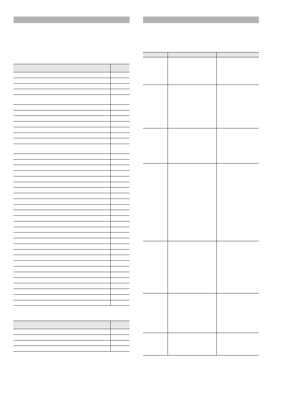
Troubleshooting
When there is a malfunction, the status light on the sensor amplifier
lights in red.
If you are using a DL Series Communication Unit (excluding DL-RB1A),
details of the error can be checked via the Communication Unit. See
the DL Series manuals for information on using the Communication
Units.
Item
Reference
chapter
Origin Alignment
Chapter 3
Setting the Tolerances
Chapter 3
HH/Setting the HH/LL Criterion Value
Chapter 3
Preset Function (Adding or Subtracting a Desired Value)
Chapter 3
Bank Function (Registering Multiple Criterion Values and
Preset Values)
Chapter 3
Reset Input (Resetting Internal Values)
Chapter 3
Hysteresis
Chapter 3
Initialization (Initial Reset)
Chapter 3
Judging with the Current Value
Chapter 4
Judging after the Detection Value is Stabilized
Chapter 4
Judging by the Maximum Value (Peak Hold)
Chapter 4
Judging by the Minimum Value (Bottom Hold)
Chapter 4
Judging with the Difference between Maximum and
Minimum Values (Peak to Peak Hold Detection Mode)
Chapter 4
Holding HIGH/LOW Output (NG Hold)
Chapter 4
Detection Mode
Chapter 5
Hold Update Method
Chapter 5
Response time
Chapter 5
Timing Type
Chapter 5
Self-timing Level
Chapter 5
Self Timing Delay Types
Chapter 5
User-specified Delay Time
Chapter 5
Static Hold Delay Stability
Chapter 5
Static Hold Delay Stability Width
Chapter 5
Measurement Direction
Chapter 5
Multiplier
Chapter 5
Batch Input Settings
Chapter 5
Special Output Setting
Chapter 5
Limit Output HH Side Teaching
Chapter 5
Limit Output HH Side Criterion Position Setting
Chapter 5
Limit Output LL Side Teaching
Chapter 5
Limit Output LL Side Teaching Criterion Position Setting
Chapter 5
Select Preset Data
Chapter 5
Store Preset Value
Chapter 5
Preset Point
Chapter 5
Power Save Function
Chapter 5
Jam Detection Function
Chapter 5
Jam Detection Teaching
Chapter 5
Jam Detection Checkpoint Setting
Chapter 5
Calculation Setting Mode
Chapter 5
Timing Chart
Chapter 5
Item
Reference
chapter
List of Optional Parts
Chapter 1
Replacing the Contact
Appendix
Replacing the Dust Boot
Appendix
How to Mount the Lift Lever
Appendix
Problem
Cause
Corrective action
Sensor head
error
• The sensor head is
disconnected.
• The sensor head cable is
broken.
• The sensor head is
damaged.
• Connect the sensor
head.
• Replace the sensor
head cable.
• Replace the sensor
head.
EEPROM
error
• Failed to write data.
• Turn the equipment off
and on, and perform
initial reset. (If this
does not solve the
problem, the
equipment may be
damaged, or may have
reached the end of its
service life. Replace
the amplifier unit.)
Jam
detection
error
• The spindle is jammed.
(When using the jam
detection function)
• If the spindle is
jammed and does not
move, replace the
sensor head.
Use a Communication
Unit to check that the
timing input is
appropriate.
Self timing
delay error
• The value fell below (rose
above) the timing level
during the set delay time.
• The value fell below (rose
above) the timing level
before the detection status
was stable and the
criterion level (P.V. value)
was fixed when using
static hold internal timing.
• The value rose above (fell
below) the timing level,
then fell below (rose
above) the timing level
before the criterion level
(P.V. value) was fixed when
using delay timer internal
timing.
• Make sure that the
value does not fall
below (rise above) the
timing level before the
criterion value is fixed.
Alternatively, lengthen
the static hold delay
stabilizing amplitude
so that the criterion
value can be easily
fixed.
Unit number
error
• When using the calculation
function, the number of the
expansion unit when the
power is turned ON differs
from the number of the
expansion unit in the
memory of the main unit
when the calculation is set.
• When using the calculation
function, a model other
than the GT2-500/70
Series is added.
• Reset the calculation
mode or perform initial
reset of the main unit.
Perform initial reset via
the Communication
Unit. See the DL
Series manuals for the
method.
Calculation
error
• When using the reference
difference calculation
function, an error occurred
in the main unit.
When using other than the
reference difference
calculation function, an
error occurred in an
expansion unit.
• Check each main/
expansion unit for the
cause of the error.
Calculation
only mode
error
• The sensor head is
connected to the main unit
in which the calculation
only mode is set.
• Remove the sensor
head from the main
unit or set a mode
other than the
calculation only mode.