Contact, How to replace the dust seal, Amplifier part names and descriptions – KEYENCE GT2-500 Series User Manual
Page 6: How to replace the contact, How to mount the lift lever
6
GT2-500-M-E
•
Detaching the air tube
To detach the air tube, (1) press down on the release ring, (2) pull
out the tube.
● For GT2-A12K/A12/A32/A50 when an IP67 enclosure
rating is required
To maintain an IP67 enclosure rating for GT2-A12K/A12/A32/A50,
the following must be satisfied:
•
Firmly connect tubing with
2.5 mm inner diameter to the exhaust
port until it bottoms out.
Ensure that the tube end is free of dirt or water.
•
Tighten the screw of the exhaust valve with a torque of 0.5 to 0.6 N m.
If the screw is loose, the IP67 rating cannot be guaranteed.
● Adjustment of Spindle Movement Speed
To adjust the spindle movement speed, install a speed controller
between the cylinder and the air supply. Using OP-87970 is
recommended.
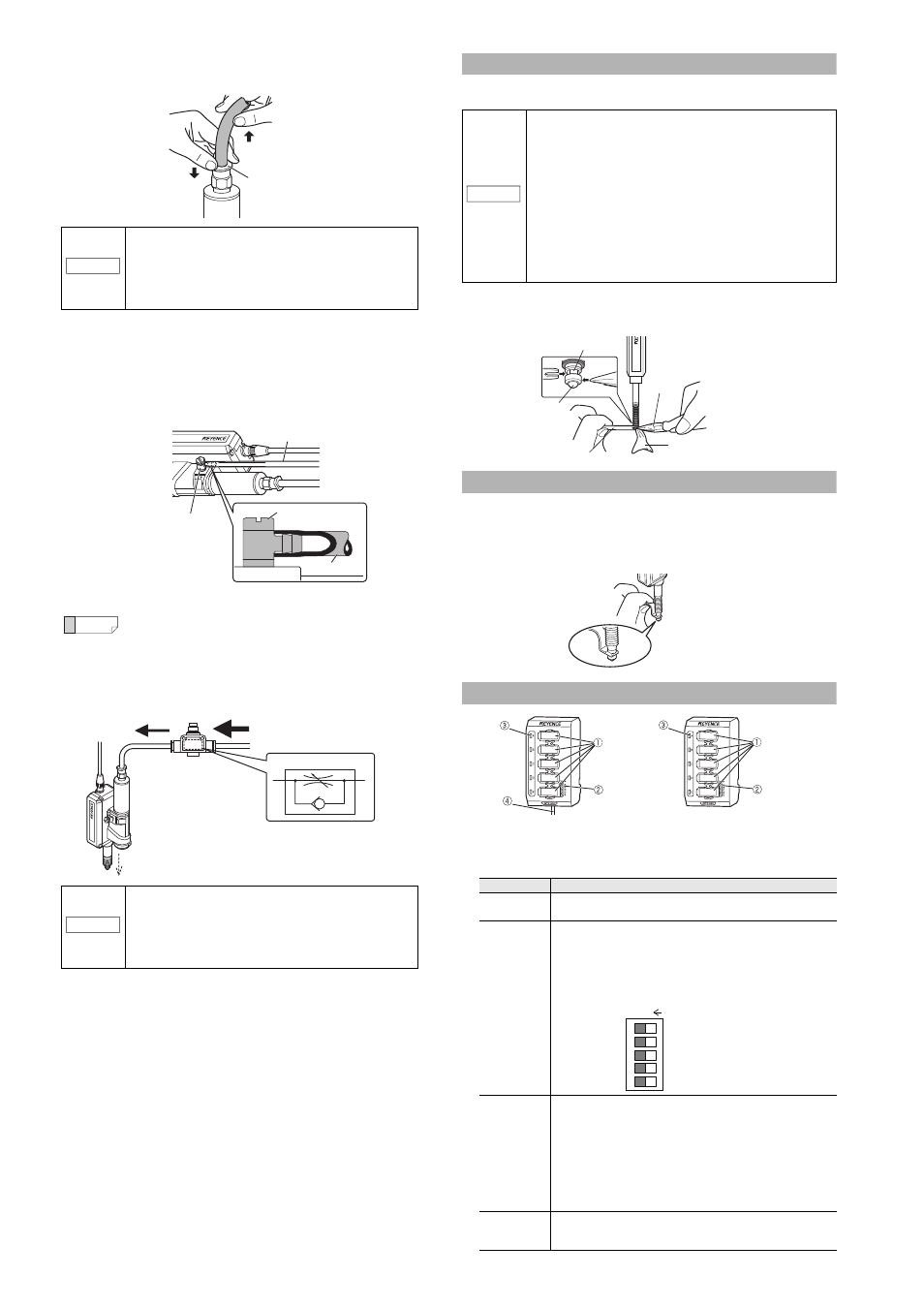
Contact
This section describes how to replace the contact, and how to mount
the lift lever.
■
How to replace the contact
While securing the spindle with the accessory key wrench, detach
the contact with pliers. Then attach a new contact.
How to replace the dust seal
Refer to the instruction manual included with the replacement dust seal
(OP-87932).
■
How to mount the lift lever
Mount the lift lever (OP-84397) between the spindle and the contact.
Secure the spindle with the lift lever and attach/detach the contact.
Amplifier part names and descriptions
Up to 5 sensor heads can be connected to 1 main unit/expansion
unit amplifier. Up to 2 expansion units can be added to 1 main unit.
Therefore, up to 15 sensor heads can be connected in total.
NOTICE
• Before detaching the tube, be sure to stop any air
flow.
• Press down on the release ring evenly from both
sides, and pull the tube out. Uneven pressure may
result in damage to the tube or damage to the
operation of the air cylinder.
Reference
By loosening the screw of the exhaust valve, you can
change the exhaust port angle.
NOTICE
• To further decrease spindle movement speed, use
a coil-shaped tube (OP-87986) or similar to
increase the distance between the air supply hole
and the speed controller.
• The speed controller will not operate if installed in
the reverse direction.
Release ring
(2)
(1)
Screw
Air tube
Air tube
Exhaust valve
Speed controller
Air supply
Indication symbol
Adjusting the speed.
NOTICE
• Detach the sensor head from the device or fixture
(metal plating, etc.) before replacing the contact.
• When applying pliers to the contact, be sure not to
rotate the main part and cover the contact with a cloth.
• Never apply tightening torque over 0.2 N m when
attaching a contact.
• Fix the roller contact (OP-77680) or the offset contact
(OP-77683) with the fixing nut in the same direction as in
actual use.
• Applying an adhesive, a thread locking agent, is
recommended to prevent the nut from getting loose.
• Position the roller contact carefully in the proper
direction. Care must be taken not to apply misdirected
force to the shaft.
Item
Explanation
Sensor head
connector
Connect to a sensor head cable with a sensor head attached.
Refer to "Connecting the amplifier" (page 3) for details.
DIP switch
Channels set to ON (enable) can recognize sensor heads.
The factory default setting for all switches is ON.
Switch channels that will not be used to OFF (disable).
Be sure to change DIP switch settings with the power off.
If the equipment is turned on while the DIP switch settings are
changed, setting changes will not be effective.
Changes are applied when the power is turned on.
Status light
Lit in green:Normal. Lights when the DIP switch is set to ON
(enabled), and the sensor heads are corrected properly.
Lit in red:
Error. Lights when the DIP switch is set to ON (enabled),
and there is an error.
See page 8 for information on checking errors and taking
corrective action.
Not lit:
Disabled Stays unlit when the DIP switch is set to OFF
(disabled).
If a sensor head is connected, it will not be automatically
recognised (the sensor head indicator will not light up).
Power cable
Supplies power. The cable is 2 m long.
Expansion units do not have power cables. Power is supplied to
expansion units through the main unit.
Spindle
Contact
Key wrench
Pliers
Cover the contact
with a cloth
GT2-500 (Main unit)
GT2-550 (Expansion unit)