Communication specifications, Sensor amplifier id number assignments, Commands and responses – KEYENCE DL-RS1A/IG User Manual
Page 9: Overview of commands and responses
7
Communication Specifications
This section provides the communication specifications of DL-RS1A and describes how to configure the unit.
Communication Specifications
The following table lists the communication specifications for DL-RS1A.
For communication settings, refer to page 2.
Sensor Amplifier ID Number Assignments
When the main sensor amplifier that is connected to DL-RS1A supports expansion units, the main
sensor amplifier ID number "00" is automatically assigned to the main unit and ID numbers "01 to 14"
to the expansion units.
You
cannot
change the assignment of sensor amplifier ID numbers.
■
DIN rail mount sensor amplifiers
■
Panel mount sensor amplifiers
Item
Specifications
Communication method Full duplex
Synchronization method Asynchronous
Transmission code
ASCII
Communication speed
2400, 4800, 9600, 19200, 38400 bit/s (Factory default: 9600 bit/s)
Data bit length
7 or 8 bits (Factory default: 8 bits)
Parity check
None, even, odd (Factory default: none)
Stop bit length
1 bit
Data delimiter
Receive: automatically detect CR or CR + LF
Send: fixed to CR + LF
Point
ID No. 00
Main
Exp.
Exp.
Exp.
Exp.
01
02
04
05
Sensor amplifier
DL-RS1A
ID No.
Sensor amplifier
00
01
02
04
05
Main
Exp.
Exp.
Sensor amplifier
Exp.
Exp.
DL-RS1A
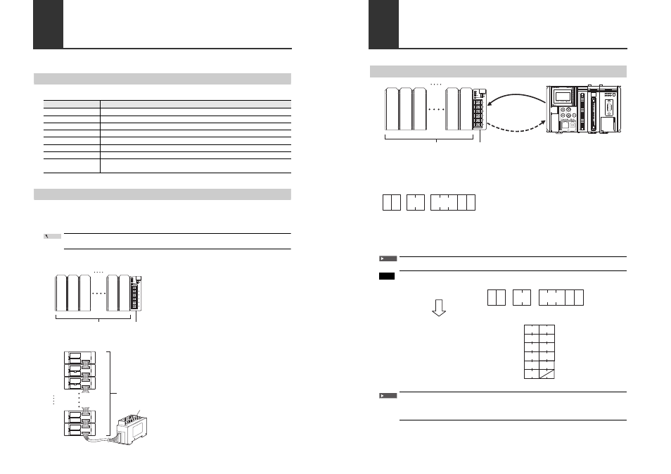
Commands and Responses
Overview of Commands and Responses
■
Command format
You can send specific commands based on ASCII codes from an external device to DL-RS1A.
For information on the parameters used in the command, refer to "Parameters of Commands and
Responses" (page 10).
Sample command format structure
(1) With the first two bytes, specify the communication command.
(2) Specify the ID number assigned to the target sensor amplifier using two digits (ASCII characters).
(3) Specify the data number for the data you want to read from or write to the sensor amplifier using
three digits (ASCII characters).
(4) Insert CR or CR + LF as the command delimiter.
You must use commas (,) to separate (1), (2), and (3).
To read the "Hold function setting (data number: 134)" from an expansion unit of an active
IG Series (ID number: 01):
From an external device, 11-byte data will be sent to the DL-RS1A.
The last byte of the command you send must be CR (0DH) or LF (0AH). Specifying a value
other than CR or LF results in an error response (error number: 00). For information on the
error responses, refer to "Error numbers" (page 16).
ID No. 00
Main
Exp.
Exp.
Exp.
Exp.
01
02
04
05
Sensor amplifier
DL-RS1A
External device like PLC or PC
Response
or
error response
Command or DRQ input
S
(1)
(2)
(3)
(4)
R
CR LF
ID No.
Data No.
,
,
Important
Example
S
(53H) (52H)
(2CH)(31H) (33H) (34H)(0DH)(0AH)
(2CH)(30H) (31H)
R
CR LF
0 1
1 3 4
,
,
Command :
S
(53H)
,
(2CH)
R
(52H)
0
(30H)
1
(31H)
1
(31H)
,
(2CH)
3
(33H)
4
(34H)
LF
(0AH)
CR
(0DH)
ASCII character conversion :
Data memory 0
Data memory 1
Data memory 2
Data memory 3
Data memory 4
Data memory 5
5352
H
Value to store in
data memory (hexadecimal)
2C30
H
362C
H
3130
H
310D
H
0A00
H
bit
15
bit
0
Important