KEYENCE DL-RS1A/IG User Manual
Page 16
14
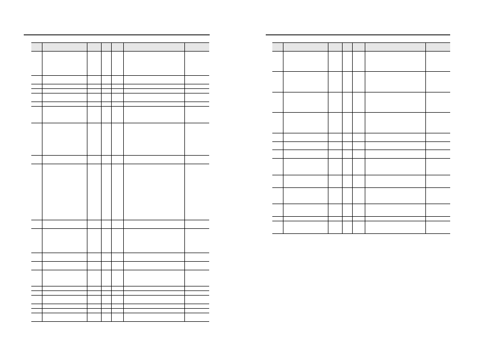
Parameters of Commands and Responses
115
Sub display's screen
*
1
R/W
0: R.V. value screen
1: Analog output screen
2: HIGH setting value screen
3: LOW setting value screen
4: Shift target value setting screen
5: Calculated value display screen
0
116
Tolerance tuning Tolerance
setting width*
9
**.***
6
R/W
00.000 to 99.999
00.100
117
Calibration function SET1
±**.***
7
R/W
-99.999 to +99.999
+00.000
118
Calibration function SET2
±**.***
7
R/W
-99.999 to +99.999
+05.000
119
Calibration Function
*
1
R/W
0: Standard
1: User setting
0
120
System parameter*
10
**
2
R/W
0 to 15
00
129
Calculation function*
11
*
1
R/W
0: The calculation function is not used.
1: Addition mode
2: Subtraction mode
3: 2 Heads mode
0
130
Measurement mode
*
1
R/W
0: Edge control/Positioning mode
1: Outer diameter/Width measurement mode
2: Inner diameter/Opening measurement mode
3: Glass edge mode
4: Pin position measurement mode
5: Pin interval judgment mode
6: Pin diameter judgment mode
7: Specified edges interval measurement mode
0
131
Measurement direction
*
1
R/W
0: Top
1: Bottom
0
132
Averaging*
12
**
2
R/W
0: hsp
1: 1
2: 2
3: 4
4: 8
5: 16
6: 32
7: 64
8: 128
9: 256
10: 512
11: 1024
12: 2048
13: 4096
05
133
Output mode
*
1
R/W
0: NO (Normally Open)
1: NC (Normally Close)
0
134
Hold function setting
*
1
R/W
0: Sample hold
1: Peak hold
2: Bottom hold
3: Peak-to-peak hold
4: Auto peak hold
5: Auto bottom hold
0
135
Auto peak hold or Auto bottom
hold Trigger level*
7
±**.***
7
R/W
-99.999 to +99.999
+00.100
136
Timing Input
*
1
R/W
0: Level
1: Edge
0
137
Delay Timer
*
1
R/W
0: Delay timer off
1: On delay timer
2: Off delay timer
3: One shot timer
0
138
Timer value
****
4
R/W
1 to 9999
0060
139
Hysteresis*
9
**.***
6
R/W
0 to 99.999
00.010
140
Analog Output Scaling
*
1
R/W
0: Initial state
1: Free range
0
141
Analog output Lower limit*
7
±**.***
7
R/W
-99.999 to +99.999
+00.000
142
Analog output Upper limit*
7
±**.***
7
R/W
-99.999 to +99.999
+10.000
143
External input*
13
*
1
R/W
0: Initial state
1: User setting
0
Data
No.
Data name
Data
format*
1
No. of
bytes
Attribute*
2
Data range
Default value
Parameters of Commands and Responses
*1
In the Data format column, "±" indicates that the value can be either "+" or "-" and "*" signifies a
number from "0 to 9".
*2
Indicates that the data can only be read from (R), can only be written to (W), or can be both read
from and written to (R/W) the sensor amplifiers.
*3
The command is executed only when the data is changed from 0 to 1. To re-execute the
command, first change the setting to 0, then change it to 1. Otherwise, the command is not
executed.
If the sensor amplifier is turned OFF after the standard waveform registration is performed, the
previous state before the standard waveform registration is performed is restored. If you wish to
keep the standard waveform registration even after the power is turned OFF, set the saving the
standard waveform function to ON.
If the sensor amplifier is turned OFF after the zero shift is performed, the previous state before
the zero shift is performed is restored. If you wish to keep the zero shift state even after the
power is turned OFF, set the saving zero shift value function to ON.
144
External input 1*
13
*
1
R/W
0: Zero shift input
1: Bank A input
2: Bank B input
3: Laser emission stop input
4: Not use
0
145
External input 2*
13
*
1
R/W
0: Reset input
1: Bank A input
2: Bank B input
3: Laser emission stop input
4: Not use
0
146
External input 3*
13
*
1
R/W
0: Timing input
1: Bank A input
2: Bank B input
3: Laser emission stop input
4: Not use
0
147
External input 4*
13
*
1
R/W
0: Gain input
1: Bank A input
2: Bank B input
3: Laser emission stop input
4: Not use
4
148
Saving the standard waveform
function
*
1
R/W
0: OFF
1: ON
0
149
Saving zero shift value function
*
1
R/W
0: OFF
1: ON
0
150
Interference prevention
function*
14
*
1
R/W
0: OFF
1: ON
0
151
Display Digit
*
1
R/W
1: 0.001
2: 0.01
3: 0.1
4: 1
2
152
Power save function
*
1
R/W
0: OFF
1: Half
3: All
0
153
Position monitor
*
1
R/W
0: Initial state
1: OK/NG display
2: Red OFF
3: OFF
0
154
Display color
*
1
R/W
0: GO Green
1: GO Red
2: Always Red
0
155
Edge check function Number of edges
**
2
R/W
0-99
01
156
Edge check function
*
1
R/W
0: OFF
1: Setting A
2: Setting B
0
Data
No.
Data name
Data
format*
1
No. of
bytes
Attribute*
2
Data range
Default value