Time frames of communication response time – KEYENCE DL-RS1A/IG User Manual
Page 20
18
Communication Response Time
• For the IG Series, when the data to which the setting written onto the sensor amplifier
using SW command and AW command is reflected is read using the reading command
(M0, MS) or DRQ input, perform this operation after additional time T elapses after the
response from the DL-RS1A is finished.
Time T varies depending on the data number.
(1) Data number corresponding to T=Response time (When the calculation function is
used: Response time + T2)
If reading is performed before T elapses, the data prior to the setting change is read.
• Data number 132: Averaging
• Sensitivity setting of the BANK currently selected (example: When the current BANK
is BANK 0, data number 068: sensitivity setting (BANK 0))
• If the sensitivity setting of the BANK currently selected is User: Binarize level or Filter
value (example: When the current BANK is BANK 0, data number 069: User Binarize
level (BANK0) and data number 070: User Filter value (BANK 0))
(2) Data number corresponding to T=Response time (When the calculation function is
used: Response time + T2)
If reading is performed before T elapses, -99.998 meaning "-----" is read as a P.V. value.
• Data number 059: Bank function
• Data number 130: Measurement mode
(3) Data number corresponding to T=Response time + 100 ms
If reading is performed before T elapses, -99.998 meaning "-----" is read as a P.V. value.
• Data number 129: Calculation function
(4) Data number corresponding to T=0 (When the calculation function is used: T2)
• Data numbers other than (1) to (3)
Point
Communication Response Time
Time Frames of Communication Response Time
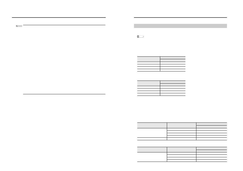
This section describes the communication time frames (T2 to T6).
The maximum time required is shown for each time frame. However, depending on the
actual environment, it may require more time.
■
T2 (DL-RS1A data processing time)
For information on the calculation function, refer to the manual supplied with the sensor amplifiers.
●
When calculation function of sensor amplifiers is OFF
*
* This table also applies to the sensor amplifiers that do not have the calculation function.
●
When calculation function of sensor amplifiers is ON
■
T3 (Command send time from external device)
Refer to the manual supplied with the external device connected to DL-RS1A.
■
T4 (DL-RS1A command processing time)
The processing time varies according to the command sent from the external device.
●
Read commands
●
Write commands
Reference
Number of connected
sensor amplifiers
Data processing time (T2)
IG Series
1
5 ms
2
10 ms
3
12 ms
4
16 ms
Number of connected
sensor amplifiers
Data processing time (T2)
IG Series
1
5 ms
2
10 ms
3
12 ms
4
16 ms
Communication command
Number of connected
sensor amplifiers
Command processing time (T4)
IG Series
SR
1
11.5 ms
2
14 ms
3
15 ms
4
17 ms
M0/MS/DRQ input
1 to 4
4 ms
Communication command
Number of connected
sensor amplifiers
Command processing time (T4)
IG Series
SW
1
19 ms
2
24 ms
3
28 ms
4
36 ms